Power / Solar Charge Controllers
User Guide for iTechworld Control Hub
Quick guide for the iTechworld Control Hub. Learn about installation, wiring switches, battery setup, connecting chargers, and technical specifications.
Table of contents
Manual images
Click an image to enlargeQuick Guide
The iTechworld Control Hub is a 12V power management solution featuring five illuminated rocker switches with replaceable fuses, an advanced battery monitor with a 500A shunt, and multiple output options including cigarette lighter sockets, USB-A, USB-C, and 50A Anderson plugs. It is designed for versatility in 12V systems.
Unit Diagram
The unit features the following key components:
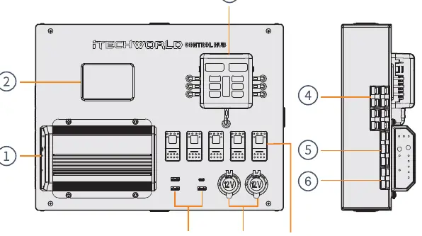
- Optional DCDC Charger: Integrated charging management.
- Advanced Battery Monitor: Displays state of charge, voltage, amperage, and wattage.
- Fuse Box: Protects individual circuits.
- In/Out 50A Andersons: High-current connection points.
- DCDC Inputs: Dedicated inputs for alternator and solar (on DCDC models).
- Rocker Switches: 5 x 20A backlit switches for controlling accessories.
Wiring Switches
- Ensure the unit is disconnected from the battery before starting.
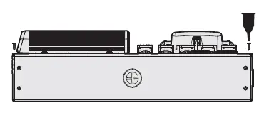
- Remove the 4 screws to open the Control Hub lid.
- Select appropriate spade and ring terminals for your accessory wiring.
- Cut the grommets on the side or bottom of the unit to route wires.
- Strip 1cm of insulation from cables and crimp terminals.
- Connect the spade terminal to the bottom blank tab on the switch.
- Connect the negative ring terminal to a spare screw position on the negative bus bar.
- Tuck cables in and re-fasten the lid.
Battery Installation
- Remove the 4 screws and open the Control Hub.
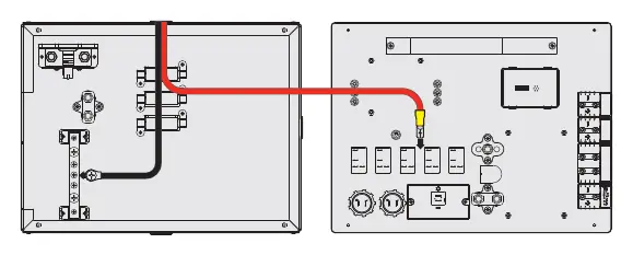
- Route battery wires through the grommets on the side or bottom.
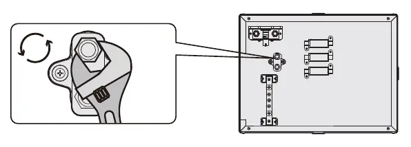
- Remove the bolt and washer from the positive and negative terminal posts on the rear.
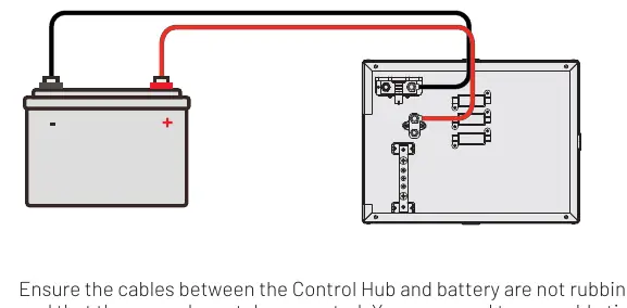
- Attach the negative cable to the B side of the shunt and the positive cable to the positive terminal.
- Fasten the bolts securely.
- Connect the other end of the cables to the battery, starting with the positive terminal.
- Ensure cables are supported and not rubbing.
Battery Monitor Setup
Access the settings menu by pressing and holding the SET button:
- SET1 (Overvoltage): Set 0.5V above the battery's stated maximum voltage.
- SET2 (Undervoltage): Set the voltage at 0% capacity (e.g., 10.5V for Lithium).
- SET3 (Overcurrent): Match with the battery's rated maximum current.
- SET4 (Capacity): Set to the actual capacity of the connected battery.
- SET5 (Percentage): Set current battery percentage to 100% (recommended to charge to 13.5V first).
- SET6 (Backlight): Adjust screen brightness.
Connecting Chargers
The Control Hub supports multiple charging methods:
- AC Charger: Connect to any in/out Anderson plug.
- Regulated Solar Panel: Connect to any in/out Anderson plug.
- Alternator: Connect to the DCDC charger alternator input using the Plug & Play DCDC Wiring Kit.
- Unregulated Solar Panel: Connect to the DCDC charger solar input Anderson plug.
Note: Solar panel open circuit voltage must not exceed 32V.
Safety Precautions
- The lid must remain closed and screwed tight during operation.
- Do not allow metal objects to fall into the unit or ports.
- Do not use with life support systems or medical devices.
- Ensure the charging profile matches your battery type to prevent fire or damage.
- Do not expose the unit to water, rain, or snow.
Manufacturer information
iTechworld
Practical help
Common problems
Solar panel not charging
Ensure the solar panel open circuit voltage does not exceed 32V.
Battery monitor reading inaccurate
Charge the battery to 13.5V before setting the monitor to 100% in the settings menu.
Accessory not working
Check the replaceable fuse on the corresponding rocker switch.
Before use
- Ensure the unit is disconnected from the battery before performing any wiring.
- Verify the battery type (Lithium, Lead Acid, Gel, AGM, Calcium) matches the charging profile.
- Ensure the lid is closed and screws are tightened before powering devices.
- Check that all cable connections are secure and not rubbing against the casing.
- Verify that the solar panel open circuit voltage is below 32V.
Specs in practice
- IP20 (Monitor)
- Protection rating for the battery monitor; indoor use only.
- IP67 (DCDC Charger)
- High level of protection against dust and water immersion.
Images and diagrams
- Unit Diagram: Identifies the location of the DCDC charger, battery monitor, fuse box, and various output ports.
- Wiring Diagram: Shows the correct connection path for positive and negative cables to the battery and shunt.
Model compatibility
- Compatible with Lithium LiFePO4, Lead Acid, Gel, AGM, and Calcium batteries.
- Solar panel open circuit voltage must not exceed 32V.
- DCDC charger models require specific wiring kits for alternator connection.

Manual page author
Michael Turner
Technical manual editor
Reviews PDF manuals for structure, safety notes, and practical product details so readers can find the right information quickly.