Power / Power Management Systems
User Manual for Projecta Intelli-Wave Pure Sine Wave Inverter
Comprehensive user guide for the Projecta Intelli-Wave Pure Sine Wave Inverter (IP2000, IP3000 series). Includes installation, wiring, remote control setup, troubleshooting, and technical specifications.
Quick answers from the manual
Quick answer
- The Projecta Intelli-Wave is a pure sine wave inverter for 12V/24V systems. It features an automatic transfer switch, ECO mode, and RCD protection. Installation requires a licensed electrician for AC wiring. p. 3, 6, 9
Key actions
- Mounting: Ensure 10cm clearance for ventilation. p. 7
- DC Wiring: Connect red to positive (+), black to negative (-). Use recommended fuse. p. 8
- AC Wiring: Requires licensed electrician. p. 9, 10
First start
- Turn On/Off switch to ON. Inverter will beep during self-analysis. p. 15
Problems and fixes
Low Battery Voltage
Recharge battery, check cable size/connections.
p. 16
Overload
Reduce appliance load.
p. 16
Over Temperature
Turn off and allow to cool.
p. 16Maintenance and reset
- Fuses should only be checked or replaced by a qualified electrical appliance repairer. p. 19
Technical specifications
| Parameter | Value | Meaning | Pages |
|---|---|---|---|
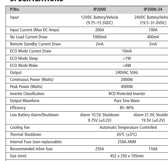
| Continuous Power | 2000W / 3000W | Maximum continuous power output. | p. 4, 5 |
| Output Waveform | Pure Sine Wave | Type of AC output. | p. 4, 5 |
| Efficiency | 85-90% | Inverter efficiency rating. | p. 4, 5 |
Where to find it in the PDF
- Safety Information p. 2
- Specifications p. 4, 5
- Wiring Diagrams p. 8, 9, 10
Table of contents
Manual images
Click an image to enlargeQuick guide from the manual
The Projecta Intelli-Wave Pure Sine Wave Inverter is designed to convert DC battery power into 240V AC mains power. It is suitable for sensitive electronics, medical equipment, and appliances. Key features include an automatic AC transfer switch, ECO mode for power saving, and RCD safety protection. Installation must be performed in a dry, well-ventilated area, and all 240V AC wiring must be completed by a licensed electrician.
Product Overview
The front panel features an LCD screen, RCD safety switch, AC output sockets, and control buttons (Volts, Watts/Load, ECO). The rear panel contains the fan, DC input terminals (positive and negative), and AC input/output wiring terminals.
Mounting Instructions
The inverter should be mounted in a dry, cool, and well-ventilated area, as close to the batteries as possible but not in the same compartment. Ensure at least 10cm of clearance from the end plates for cooling fan ventilation. The unit can be mounted horizontally or vertically using the mounting flanges.
Wiring the Inverter
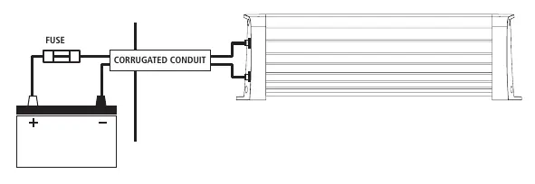
DC Wiring: Use appropriate cable sizes as specified in the manual to prevent voltage drop. Install a high-current fuse or circuit breaker in the positive line as close to the battery as possible. Connect the red cable to the positive (+) terminal and the black cable to the negative (-) terminal.
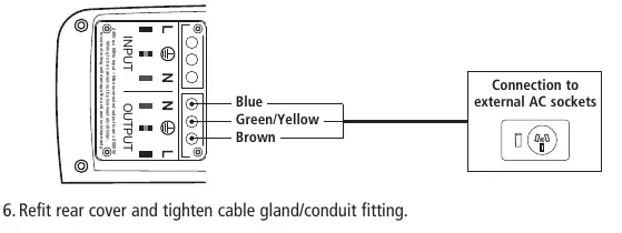
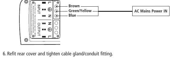
AC Wiring: AC output can be wired directly from the rear terminals. Ensure a licensed electrician performs all 240V AC wiring. Follow the terminal markings: Earth (Green/Yellow), Neutral (Blue), and Active (Brown).
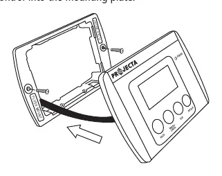
Remote Control Display
The remote allows monitoring and control of the inverter. It can be flush-mounted or surface-mounted. To operate the inverter via remote, the main unit's On/Off switch must be set to ON. The remote displays battery voltage, power draw, and ECO mode status.
Operating Instructions
Turn the inverter On/Off switch to ON. The unit will perform a self-analysis. To prevent overloading, turn on appliances one at a time. ECO Mode can be set to activate after 1 hour, 3 hours, or automatically (on) to reduce power consumption when no load is detected.
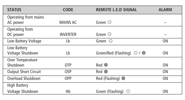
Troubleshooting
If the inverter turns off, check for fault codes on the LCD screen. Common issues include low battery voltage, overload, or over-temperature. Ensure the RCD switch is in the 'down' position (red indicator visible) for normal operation.
Practical help
Common problems
Inverter turns off unexpectedly
Check for overload, low battery voltage, or poor cable connections. Refer to the 'Faults & Errors' table.
Inverter will not run appliance
The appliance may be an inductive or capacitive load requiring a high surge current. Ensure the appliance is suitable for the inverter's capacity.
Fan does not run
The cooling fan is temperature-controlled and only operates when necessary.
Before use
- Ensure the installation area is dry, cool, and well-ventilated.
- Verify the battery voltage matches the inverter input (12V or 24V).
- Use the recommended cable size and length to prevent voltage drop.
- Install a fuse or circuit breaker in the positive line near the battery.
- Ensure the RCD switch is in the 'down' position (red indicator visible).
Specs in practice
- Pure Sine Wave
- Replicates mains power, making it safe for sensitive electronics like medical equipment and computers.
- RCD Safety Switch
- Detects earth leakage and disconnects power sockets to protect against electrocution.
Images and diagrams
- Front panel: Displays LCD screen, RCD switch, and AC output sockets.
- Rear panel: Contains DC input terminals, cooling fan, and AC wiring terminals.
Model compatibility
- Not for use with buildings.
- Requires a licensed electrician for all 240V AC wiring.
- Not recommended for large appliances with extremely high start-up currents (e.g., large fridges).

Manual page author
David Miller
Documentation analyst
Organizes user manual content into clear summaries, with attention to model details, product context, and everyday usability.