Power / EV Chargers
User Manual for LAPP Mobility Dock
Quick guide for the LAPP Mobility Dock (002534486ML00). Learn how to safely charge your EV, understand LED status indicators, and follow proper maintenance procedures.
Table of contents
Manual images
Click an image to enlargeImportant Information
The LAPP Mobility Dock is a Mode 2 emergency charger designed for occasional, portable use. It must be operated in a safe, motionless, and vertical position. The device is intended for use on mechanically and electrically suitable, wall-mounted sockets. Warning: The device is not suitable for use with extension leads or for horizontal operation on the ground, as this poses a risk of electric shock and housing damage.
Product Components
The Mobility Dock consists of the following main parts:
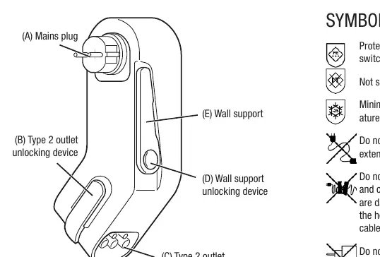
- (A) Mains plug: Connects to the wall socket.
- (B) Type 2 outlet unlocking device: Orange lever for releasing the charging plug.
- (C) Type 2 outlet: Connection point for the vehicle charging cable.
- (D) Wall support unlocking device: Knob to adjust the wall support.
- (E) Wall support: Ensures the device remains in a vertical position.
Operation
Follow these steps to charge your vehicle:
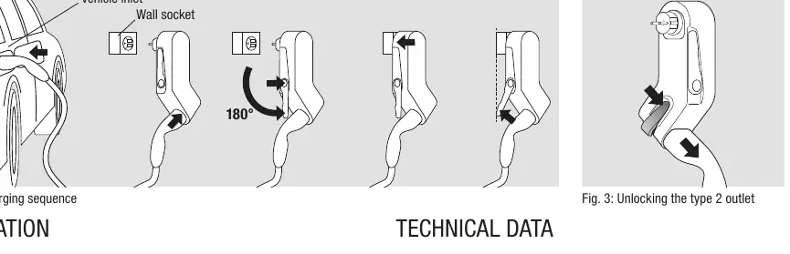
- Insert the vehicle coupling into the vehicle inlet.
- Insert the charging plug into the Type 2 outlet (C) until it clicks into place (B).
- Unlock the wall support (E) using the knob (D) and fold it out until it stops.
- Insert the mains plug (A) into a suitable wall socket so the housing hangs downwards. The device will perform a self-test.
- Turn the wall support until the Mobility Dock is supported in a vertical position.
- The device will communicate with the vehicle and release the charge.
To end charging:
- End the charging process via the vehicle (LED will light up permanently green).
- Unplug the Mobility Dock (A) from the wall socket.
- Unlock (D) the wall support (E) and return it to the starting position.
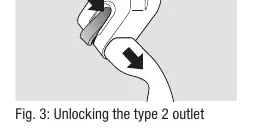
- If necessary, unlock the charging plug with the orange lever (B) and unplug it.
- Unplug the vehicle coupling from the vehicle.
- Stow the Mobility Dock and cable securely in the boot.
Status Display
The LED indicator provides information about the device status:
- Permanently off: Not in socket.
- Green (permanently on): Self-test OK, vehicle connected, standby.
- Green (flashing): Charging.
- Blue (flashing): Reduced charging (e.g., at high temperature).
- Yellow/Green (flashing): Vehicle connected, warning status display.
- White (permanently on): Self-test OK, vehicle not connected. Disconnect and connect to vehicle first.
- Red (permanently on): Temporary error (e.g., overtemperature). Device restarts automatically.
- Red (flashing): Safety error (e.g., installed upside down). Disconnect from mains for 10 seconds, rectify fault, and plug in again.
Technical Data
- Charging power: 2.3 kW
- Nominal voltage: 230V AC
- Nominal current: 10 A (Note: 8 A for France/Finland if charging cycle exceeds 2 hours)
- Frequency: 50 Hz
- Protection class: I
- IP degree: IP44
- Operating temperature: -25 °C to +45 °C
Maintenance and Care
Disconnect the Mobility Dock from the vehicle and the mains before cleaning. Clean only with a slightly damp cloth. Do not use aggressive cleaning agents.
Practical help
Common problems
Red LED permanently on
Temporary error (e.g., overtemperature). The device will restart automatically.
Red LED flashing
Safety error (e.g., installed upside down). Disconnect from the mains for 10 seconds, rectify the fault, and plug it in again.
White LED permanently on or flashing
Self-test OK, but vehicle not connected. Disconnect the Mobility Dock from the socket and connect it to the vehicle first.
Before use
- Visually check all components for damage (cracks, broken parts, dirt).
- Ensure the wall socket is suitable, properly earthed, and checked by an electrician.
- Verify the wall support is long enough to support the device in a vertical position.
- Ensure the charging cable is not damaged, bent, or twisted.
- Confirm the device is not being used with an extension cord or travel adapter.
Specs in practice
- Charging power
- 2.3 kW
- Nominal current
- 10 A (8 A limit applies in France/Finland for cycles > 2 hours)
Images and diagrams
- Fig 1: Identifies the mains plug, wall support, and Type 2 outlet.
- Fig 2: Illustrates the 5-step charging sequence.
- Fig 3: Shows how to unlock the Type 2 outlet using the orange lever.
Model compatibility
- Not suitable for IT-nets.
- Must be used in a vertical position.
- Not suitable for use with extension leads.

Manual page author
Emily Carter
User documentation editor
Prepares concise manual descriptions and highlights the most useful setup, operation, and maintenance information for readers.