Automotive / Car Audio
Installation Instructions for Metra 107-GM5B Car Audio Dash Kit
A comprehensive installation guide for the Metra 107-GM5B dash kit designed for the 2010-2012 Cadillac SRX. This guide covers dash disassembly, kit preparation, radio assembly, Axxess interface wiring, and steering wheel control...
Table of contents
Manual images
Click an image to enlargeQuick guide from the manual
The Metra 107-GM5B is an installation kit designed for the 2010-2012 Cadillac SRX. It allows for the installation of aftermarket radios while retaining factory features such as climate controls, steering wheel controls, backup camera, and OnStar. Before beginning, disconnect the negative battery terminal. Ensure you have the necessary tools: panel removal tool, Phillips screwdriver, 9/32 inch socket wrench, and T-15 Torx screwdriver.
Dash disassembly
To access the radio, you must first disassemble the center console and dash:
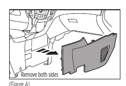
- Use a panel removal tool to unclip and remove trim panels from both sides of the center console.
- Remove the 9/32 inch screws securing the padded trim and remove it.
- Unsnap the u-shaped trim around the lower dash pocket.
- Remove the screws securing the lower portion of the control panel and pull the pocket out.
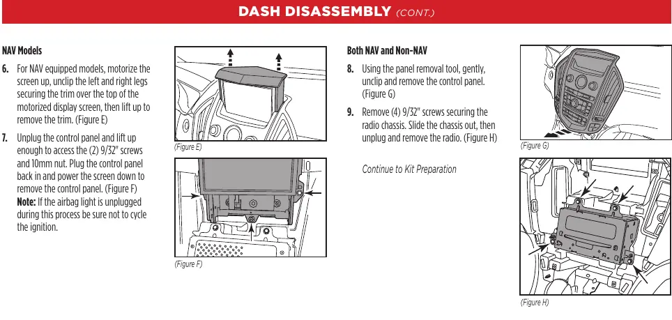
- For navigation models, motorize the screen up, remove the trim over the top, unplug the control panel, and remove the screws/nut to extract the panel.
- Unclip and remove the control panel, then remove the screws securing the radio chassis to slide it out.
Kit preparation
Prepare the factory components for the new kit:
- For non-navigation models, remove the top trim panel, factory screen, and screen bezel.
- For navigation models, remove the factory screen bezel.
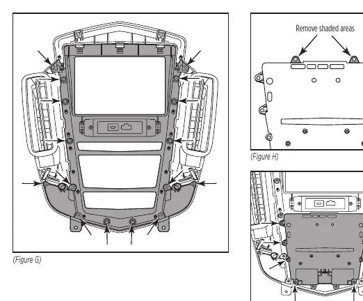
- Remove the clock panel, control button panel, and inner housing from the outer silver trim.
- Secure the 107-GM5B dash panel using factory screws.
- Cut off the top mounting legs from the main factory climate buttons and secure them to the new panel.
- Connect the lower climate controls, ensuring keyways are aligned.
Kit assembly
Depending on your radio type, follow the specific assembly instructions:
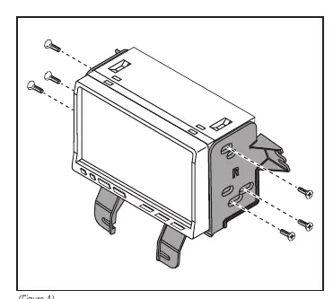
- ISO DDIN radio: Secure the radio brackets to the radio using the screws supplied with the radio.
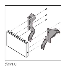
- Pioneer Modular DDIN radio: Secure the display screen to the Pioneer display brackets, connect the RGB extension cable, and secure the assembly to the dash. Attach the Pioneer chassis brackets to the radio chassis.
Axxess interface installation and wiring
The Axxess interface retains factory features. Connect the 16-pin harness and car side harness to the interface. Follow the wiring diagrams provided in the manual for your specific vehicle configuration (amplified vs. non-amplified). Ensure the pink wire with the red bullet connector is connected to the climate control harness, or climate controls will not function. Connect the yellow RCA jack to the backup camera input to retain the factory camera.
Programming and steering wheel controls
To program the interface:
- Start the vehicle and connect the car side harness. The LED will flash to indicate radio detection.
- Wait for the LED to turn solid green, indicating successful programming.
- Chime volume can be adjusted using the potentiometer on the interface.
- Steering wheel controls can be remapped or assigned dual functions by following the specific button-press sequences outlined in the manual.
Final assembly
Once all connections are verified and the interface is programmed, secure the radio/bracket assembly to the dash using factory screws. Reassemble the dash in the reverse order of disassembly.
Practical help
Common problems
Radio turns off when OnStar is activated
Ensure the brown mute wire is connected.
Climate control fails to function
Ensure the pink wire with the red bullet connector is connected to the pink wire from the climate control harness.
No sound from factory amplifier
Ensure the blue/white amp turn-on wire is connected.
Interface fails to function
Refer to the 'Troubleshooting' and 'Resetting the Axxess interface' sections.
Before use
- Disconnect the negative battery terminal.
- Verify vehicle compatibility (Cadillac SRX 2010-2012).
- Gather tools: panel removal tool, Phillips screwdriver, 9/32 inch socket wrench, T-15 Torx screwdriver.
- Identify if the vehicle has an amplifier or navigation system.
- Ensure all wiring connections are secure before testing.
Specs in practice
- 12-volt 10-amp
- Provides accessory power for the aftermarket radio.
- Potentiometer
- Used to adjust chime volume levels; turn clockwise to raise, counterclockwise to lower.
Images and diagrams
- Figure A-D (Page 2): Shows the removal of trim panels and screws for dash disassembly.
- Figure G-I (Page 6): Shows the assembly of the new dash panel and climate buttons.
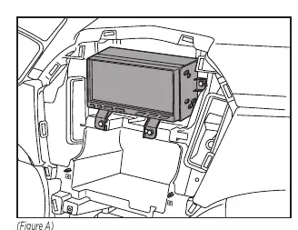
- Figure A (Page 7): Shows the ISO DDIN radio bracket attachment.
- Figure A-C (Page 8): Shows the Pioneer Modular DDIN radio assembly steps.
Model compatibility
- Designed for Cadillac SRX 2010-2012.
- Compatible with both amplified and non-amplified models.
- Retains factory climate controls, steering wheel controls, backup camera, and OnStar.

Manual page author
Emily Carter
User documentation editor
Prepares concise manual descriptions and highlights the most useful setup, operation, and maintenance information for readers.