Toys / RC Models & Drones
User Manual for Scorpion Tribunus III 06-110A / 06-160A ESC
Comprehensive user guide for the Scorpion Tribunus III 06-110A and 06-160A Electronic Speed Controllers. Includes installation, wiring, software configuration, and troubleshooting.
Table of contents
Manual images
Click an image to enlargeQuick Start Guide
The Scorpion Tribunus III ESC is a high-performance electronic speed controller designed for flight applications. Before first use, ensure you have downloaded the SPROTO software and performed the necessary throttle calibration. Always handle the ESC with respect, as connected motors can start unexpectedly.
Connecting your ESC
Proper connection is critical for safety and performance:
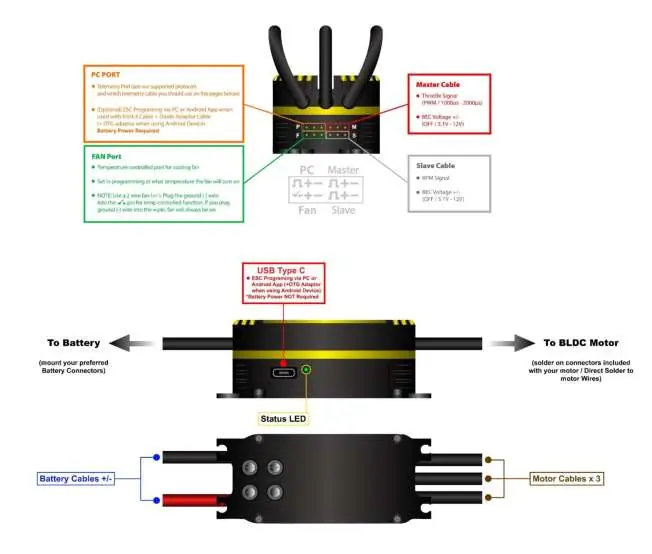
- Battery Connector: Solder a suitable connector to the red (positive) and black (negative) wires. Ensure correct polarity; reverse polarity will void the warranty.
- Motor Connection: Use bullet connectors or solder directly to the motor leads. Ensure proper insulation with heat shrink.
- Receiver/Telemetry: The Master BEC cable (red connector) connects to the Throttle channel. The Slave BEC cable (black connector) provides RPM signal and BEC power.
- Cooling Fan: Highly recommended to prevent overheating. Connect to the dedicated FAN port.
Initial Setup and Calibration
Throttle calibration is mandatory before the first flight:
- Remove the propeller or pinion from the motor.
- Turn on your transmitter and set the throttle to maximum.
- Connect the battery to the ESC.
- Wait for the beep, then move the throttle to the lowest position within 3 seconds.
- Wait for two beeps and the Power on Sound (POS) to confirm calibration.
SPROTO Software and Configuration
The SPROTO software is required for advanced settings, firmware updates, and data logging. Connect the ESC to your PC using a data-capable USB-C cable. Note that if using Unsolicited Telemetry mode, you must connect to the software within 5 seconds of powering on the ESC.
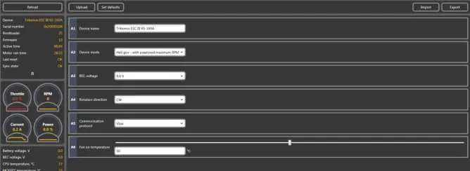
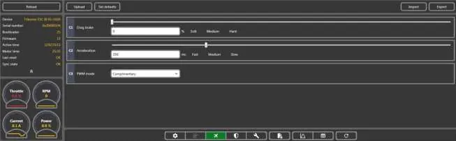
Protection Settings
The ESC includes advanced protection features to prevent damage:
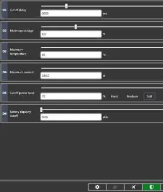
- Cut off delay: Adjusts how long the power reduction period takes when a limit is reached.
- Minimum voltage: Protects against over-discharging the battery.
- Maximum temperature: Protects the ESC from overheating.
- Maximum Current: Regulates both battery and phase current to prevent failure.
Troubleshooting
If you encounter issues, check the following:
- Connection issues: Ensure you are using a data USB cable, not a charging-only cable. Disable Bluetooth on your PC if it interferes with the COM port.
- Motor won't spin: Verify that the throttle was at 0% during initialization and that no protection functions are active.
- Overheating: Check your gear ratio and propeller size. Ensure the cooling fan is operational and airflow is not obstructed.
Practical help
Common problems
ESC will not connect to SPROTO
Ensure PC is connected to the internet, use a data USB cable (not charging only), disable Bluetooth, and connect within 5 seconds if using Unsolicited telemetry mode.
Throttle calibration fails
Ensure throttle direction is correct (1000us-2000us), no throttle hold is enabled, and the master BEC cable is connected to the throttle port.
Motor won't spin
Ensure throttle was at 0% during initialization, check phase connections, and ensure no protection functions are active.
ESC runs hot
Check gear ratio/propeller choice to avoid excessive loading, ensure cooling fan is used, and check logs for over-current warnings.
Before use
- Remove propeller or pinion before calibration
- Ensure correct polarity for battery connection
- Check if radio/servos accept 6.2V BEC
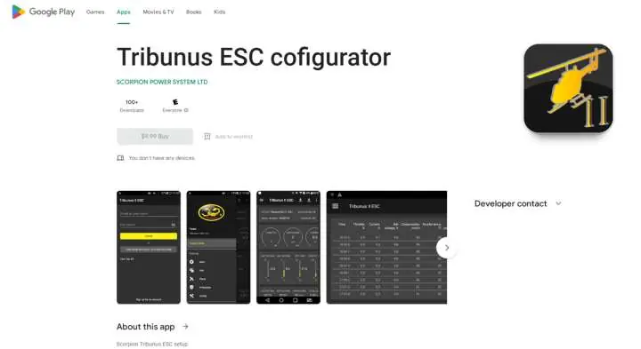
- Download SPROTO software
- Verify phase connections
Specs in practice
- Phase Current
- Current passing through motor phases; higher than battery current at partial throttle.
- Governor Mode
- Maintains constant RPM for helicopters.
Images and diagrams
- Wiring diagram shows connections for Battery, Motor, PC/Telemetry, and Fan.
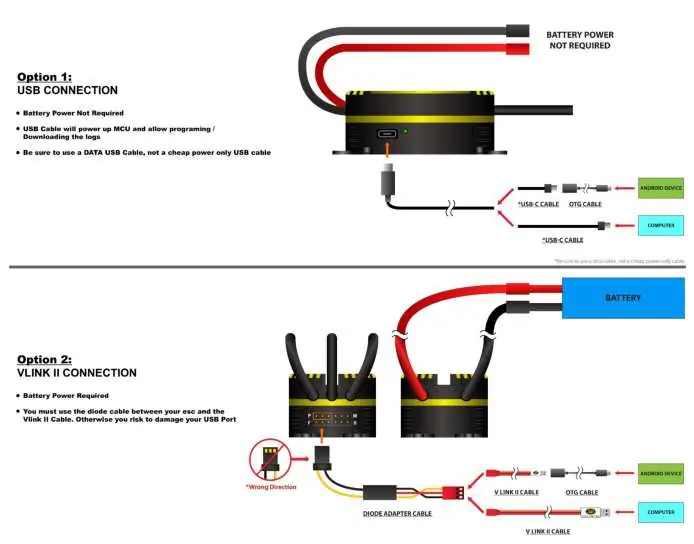
- Option 1: USB connection for programming.
- Option 2: VLINK II connection for programming.
Model compatibility
- Compatible with Mikado Vbar, Futaba, Jeti, and other systems.
- Requires SPROTO software for full configuration.
- Not designed for power supplies without precautions.

Manual page author
David Miller
Documentation analyst
Organizes user manual content into clear summaries, with attention to model details, product context, and everyday usability.