Industrial / Cleaning Systems
User Manual for Nilfisk FOOD MultiFoamer Inox
Quick guide for the Nilfisk FOOD MultiFoamer Inox. Includes installation, operation, maintenance, troubleshooting, and technical specifications for this industrial cleaning station.
Table of contents
Manual images
Click an image to enlargeQuick guide from the manual
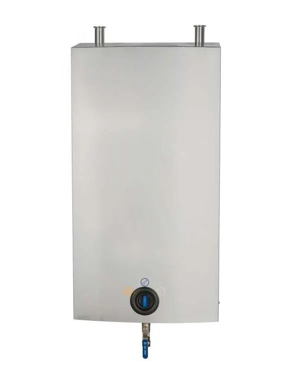
The MultiFoamer Inox is an industrial low-pressure cleaning and sanitizing station. Before use, ensure all operational staff have read the safety instructions. Always wear protective glasses and gloves when operating the unit. In case of emergency or maintenance, close the water and air supply and turn off the power.
Overview and use
The MultiFoamer is a complete hygiene and pumping station that supplies pressurized water to integrated hygiene points or connected cleaning areas. It requires a supply of water, power, compressed air, and detergents or disinfectants. The unit features a frequency-controlled pump for constant working pressure.
Installation
The unit must be mounted in frost-free rooms on a stable brick or concrete wall. Ensure the pipeline is rinsed thoroughly before connection. The unit is hung on a wall bracket and secured with two screws. Water connection must be made at the top of the unit, and a closing valve is recommended on the inlet. Electrical installation must include a separate service switch and an earth leakage circuit breaker (ELCB) with a 300 mA trip level.
Operation
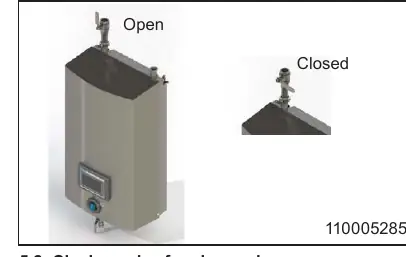
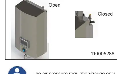
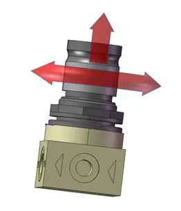
To start the system, ensure water and air supplies are open. For air pressure adjustment, remove the cover and turn the reduction valve knob: clockwise to increase pressure, counter-clockwise to decrease. To stop, turn off the water and air supply, and deactivate the chemical supply by removing the User Pack or pulling up the suction hose. Always rinse the chemical supply system after use to prevent clogging.
Maintenance and service
Preventive maintenance should be performed by an authorized service engineer at least once a year. Regularly lubricate quick couplings with waterproof grease. The unit requires periodic deliming based on water hardness (see table in the manual). Internal cleaning of the unit is recommended once a year. Do not spray inside the unit.
Troubleshooting
If the unit does not start, check the supply voltage and the flow switch adjustment. If there is no pressure or low pressure, check the water supply, clean the filter, or check the pump. If foam creation is insufficient, check the air supply, adjust air pressure, or clean/replace the non-return valve for air.
Technical specifications
The unit operates with a supply voltage of 380-500V (50/60Hz) and requires a minimum water supply pressure of 2 bar (29 psi). The maximum water temperature is 70°C (158°F). The sound level is below 70dB. Dimensions are 1310x560x470 mm.
Practical help
Common problems
The unit does not start
Check if there is supply voltage to the unit and try to readjust the flow switch.
No pressure or too low pressure
Ensure water supply is open, clean the filter, or check if the pump is leaking.
Insufficient foam creation
Check air supply, adjust air pressure in the mixing chamber, or clean/replace the non-return valve for air.
No foam creation
Ensure air supply is active, clean the mixing chamber nozzle, or delime the unit.
Before use
- Ensure water and air supply valves are open
- Verify that the unit is securely mounted
- Wear protective glasses and gloves
- Check that the chemical supply (User Pack or can) is properly connected
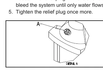
- Ensure the system has been bled of air
Specs in practice
- Max water temperature
- 70°C / 158°F
- Supply voltage
- 380-500V
Images and diagrams
- Operating diagram: Shows the flow paths for water, air, and chemicals.
- Installation diagram: Provides wall mounting dimensions and connection points.
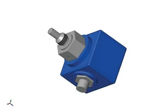
- Spare parts diagrams: Illustrate the assembly of the main block, inlet pipe, and outlet pipe.
Model compatibility
- Requires 380-500V power supply
- Requires compressed air supply (5.9 - 9.9 bar)
- Use only Nilfisk FOOD approved detergents and disinfectants

Manual page author
David Miller
Documentation analyst
Organizes user manual content into clear summaries, with attention to model details, product context, and everyday usability.