Tools / Measuring Tools
User Manual for PCE-BTM 2000A Belt Tension Meter
Comprehensive user guide for the PCE-BTM 2000A Belt Tension Meter. Includes setup, measurement procedures, force calculation formulas, and maintenance instructions.
Quick answers from the manual
Quick answer
- The PCE-BTM 2000A is a mobile device for measuring belt tension (Hz) and calculating trum force (N/lbf). It requires inputting belt mass and length for force calculations and should be used on stationary belts only. p. 8, 21
Key actions
- Calibrate the sensor p. 12, 25
- Measure belt tension p. 13, 26
First start
- Insert batteries, calibrate, and set date/time. p. 10, 23
Problems and fixes
Human vibration interference
Use a tripod to mount the sensor.
p. 13, 26Maintenance and reset
- Clean with a damp cloth; do not use abrasives. p. 4, 17
Technical specifications
| Parameter | Value | Meaning | Pages |
|---|---|---|---|
| Measurement range | 10 - 900 Hz | Frequency range for belt tension. | p. 5, 18 |
| Power supply | 3 x 1.5 V AA | Battery requirements. | p. 5, 18 |
Where to find it in the PDF
- Specifications p. 5, 18
- Measurement p. 13, 26
Table of contents
Manual images
Click an image to enlargeQuick guide from the manual
The PCE-BTM 2000A is a mobile device designed to measure belt tension (in Hz) and calculate trum force (in N or lbf). To get started, insert three AA batteries, calibrate the sensor, and enter the belt's technical data (mass per meter and trum length) into the device menu. Always ensure the machine is powered off before taking measurements.
Safety information
- Never perform measurements on running systems or rotating belts.
- Ensure the main switch of the system is off and secured against accidental restart before measuring.
- Do not use the device in explosive atmospheres.
- Do not expose the device to extreme temperatures, direct sunlight, or moisture.
- Only use the device with accessories provided by PCE Instruments.
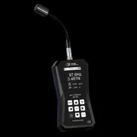
Device description
The device consists of the main unit with a display and keypad, and a sensor head connected via a sensor socket. The sensor head must be positioned parallel to the belt for accurate readings.
Getting started
- Power supply: Requires three AA alkaline batteries. The compartment is on the back, secured by two screws.
- Preparation: Connect the sensor head to the device and tighten the knurled nut.
- Calibration: It is recommended to perform a zero-point calibration after every restart. Place the device on a flat surface and the sensor head over a flat, bright surface, then select 'Calibration' in the menu.
Measurement procedure
- Enter the belt's mass (kg/m) and trum length (m) in the 'Force' menu.
- Press the 'Measuring mode' key twice to enter the measurement interface.
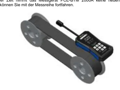
- Align the sensor head so the measuring diodes or white sensor strip are parallel to the belt.
- Place the probe in the middle of the load trum, at a distance of 10 to 25 mm from the belt.
- Make the belt vibrate (e.g., using the optional mallet) to start the measurement.
- Press the 'OK' key to save the measurement if desired.
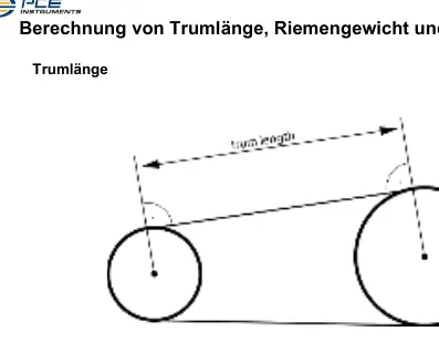
Calculations
The device can calculate trum force based on the measured frequency, belt mass, and trum length. If the trum length is not directly measurable, it can be calculated using the formula: ltrum = (lbelt - (pi * d1 + pi * d2) / 2) / 2, where lbelt is the total belt length and d1/d2 are the diameters of the pulleys.
Maintenance and disposal
Clean the device only with a damp cloth; do not use abrasives or solvents. Batteries must be disposed of at designated collection points and not in household waste. The device is subject to WEEE regulations for electronic waste.
Practical help
Common problems
Inaccurate measurements
Ensure the sensor head is parallel to the belt and maintained at a distance of 10-25 mm.
Interference from human vibration
Use the optional tripod (STAT) to mount the sensor firmly, avoiding direct contact or movement during measurement.
Cannot calculate trum force
Ensure the belt mass (kg/m) and trum length (m) are correctly entered in the 'Force' menu.
Before use
- Check the device housing for visible damage.
- Insert three fresh AA alkaline batteries.
- Connect the sensor head and tighten the knurled nut.
- Perform a zero-point calibration.
- Enter the specific belt technical data (mass and length).
Specs in practice
- Measurement range
- 10 to 900 Hz.
Images and diagrams
- The sensor head must be positioned parallel to the belt.
- The optimal distance between the probe and the belt is 10-25 mm.
- The probe should be placed in the middle of the load trum.
Model compatibility
- Compatible with V-belts, toothed belts, ribbed belts, drive belts, and conveyor belts.

Manual page author
David Miller
Documentation analyst
Organizes user manual content into clear summaries, with attention to model details, product context, and everyday usability.