Tools / Measuring Tools
Sealey STW292.V2 Digital Torque Adaptor User Manual
Quick guide for the Sealey STW292.V2 3/4" SQ Drive Digital Torque Adaptor. Includes setup, operation, memory functions, and maintenance instructions.
Quick answers from the manual
Quick answer
- The Sealey STW292.V2 is a digital torque adaptor for use with standard ratchets or breaker bars, featuring a 200-1000Nm range, memory for 50 readings, and LED/audible alarms. p. 1
Key actions
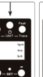
- Power On: Press the Power button. p. 2
- Change Units: Press Mem and Peak/Trace buttons together. p. 2
- Set Target Torque: Use (+) or (-) buttons. p. 2
First start
- Install 2x AA batteries in the rear compartment, then press the Power button. p. 2
Maintenance and reset
- Periodic calibration is required; contact your Sealey stockist. p. 3
Technical specifications
| Parameter | Value | Meaning | Pages |
|---|---|---|---|
| Range | 200-1000Nm | Operating torque range | p. 1 |
| Drive | 3/4" sq. | Square drive size | p. 1 |
Where to find it in the PDF
- Safety and Specifications p. 1
- Operation p. 2
- Maintenance p. 3
Table of contents
Manual images
Click an image to enlargeQuick guide from the manual
The Sealey STW292.V2 is a digital torque adaptor designed for use with standard ratchets or breaker bars. It features a 200-1000Nm range, memory for 50 readings, and LED/audible alarms. Important: Do not press the Mem and Power buttons simultaneously, as this enters calibration mode.
Safety
- Do not apply force when the power is off.
- Do not turn off the device while applying torque.
- Do not exceed the maximum torque value.
- Ensure all components (adaptors, extensions, sockets) are rated for the torque being applied.
- Do not use worn or cracked sockets.
- Do not submerge in water or use organic solvents for cleaning.
Operation
Preparation
Unscrew the four cross-head screws on the rear battery cover. Install two AA batteries, ensuring correct polarity. Refit the cover and tighten the screws.

Power On
Press the Power button once. The display will show "trACE" or "PtoP" and then "0.0". The device automatically shuts off after 70 seconds of inactivity.

Selecting Unit of Measurement
Press the Mem and Peak/Trace buttons together to cycle through Nm, lb.in, and kg.m.
Setting Target Torque
Use the (+) or (-) buttons to adjust the target value. When torque approaches within 20% of the target, the red LED will flash and an intermittent buzzer will sound. Stop applying pressure immediately when the target is reached.

Peak or Trace Mode
Press the Peak/Trace button to toggle between modes. "PtoP" (Peak) captures the maximum torque, while "trACE" shows real-time torque.
Memory
In "PtoP" mode, press the Mem button for at least 1 second to store a reading. The device stores up to 50 readings (P01 is the latest, P50 is the oldest).
Maintenance
- Keep batteries dry and remove them if the device is not used for a long period.
- Do not mix old and new batteries.
- Clean only with a soft, damp cloth.
- Periodic re-calibration is required; contact your Sealey stockist.
Official resources from the manual
Manufacturer information
Sealey Group
Practical help
Common problems
Device does not turn on
Check battery installation and polarity.
Inaccurate readings
Ensure the battery is not low and the device is calibrated.
Device enters calibration mode accidentally
Do not press Mem and Power buttons at the same time.
Before use
- Install 2x AA batteries with correct polarity.
- Ensure the socket is not worn or cracked.
- Verify the adaptor capacity matches the application.
- Ensure the floor is not slippery and wear non-slip shoes.
- Check that all extensions and drivers are rated for the torque.
Specs in practice
- Auto Shut Off
- After 70 seconds of inactivity
Images and diagrams
- Fig 1: Battery compartment access.
- Fig 2: Power button location.
- Fig 3: Unit selection buttons.
- Fig 4: Target torque adjustment buttons.
- Fig 5: Peak/Trace selection button.
Model compatibility
- Designed for use with a standard ratchet or breaker bar.

Manual page author
David Miller
Documentation analyst
Organizes user manual content into clear summaries, with attention to model details, product context, and everyday usability.