Lighting / Controllers & Dimmers
Installation Guide for Philips DDRC1220FR-GL Relay Controller
Quick installation guide for the Philips DDRC1220FR-GL Relay Controller. Includes wiring diagrams, channel configuration, electrical ratings, and safety requirements for professional installation.
Table of contents
Manual images
Click an image to enlargeImportant Information
This device must be installed by a qualified electrician in accordance with all national and local electrical and construction codes. The device must be housed in an approved enclosure. Crucial configuration rule: You must leave a one-channel gap between channels if they are on different phases. Additionally, to use channel 1, it must be on the same phase as the supply terminals.
Physical Installation
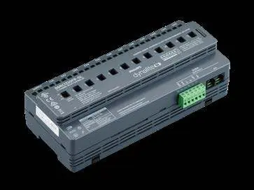
The unit dimensions are 215 mm (8.46 in) x 93 mm (3.66 in) x 64 mm (2.52 in). Ensure a minimum clearance of 45 mm (1.77 in) above and below the unit for proper ventilation. The device is rated for operation between 0°C (32°F) and 50°C (122°F) with a maximum humidity of 90%.
Wiring and Phase Configuration
The controller supports various wiring configurations:
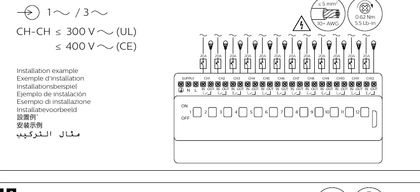
- 1-Phase / 3-Phase: CH-CH voltage must be ≤ 300 V (UL) or ≤ 400 V (CE).
- Terminal Torque: Power terminals require 0.62 Nm (5.5 Lb-in). Communication terminals require 0.4 Nm (3.5 Lb-in).
- Wire Gauge: Use 0.3-2.5 mm² (22-12 AWG) wire.
Refer to the provided wiring diagrams for specific 1-phase and 3-phase connection examples, ensuring the channel gap rule is strictly followed to prevent phase-to-phase interference.
Electrical Ratings
The output ratings per channel (CH1-CH12) are as follows:
- General Use: 16 A, 277 V (UL) / 20 A, 240 V (CE)
- Incandescent: 16 A, 277 V
- Electronic Driver: 16 A, 277 V
- Motor: 16 FLA (1 HP) at 120 V; 14.5 FLA (2.5 HP) at 240 V; 14.1 FLA (3 HP) at 277 V
- Inrush Current: 500 A
The total group rating (DDRC1220FR-GL) is ≤ 180 A.
Communication and Control
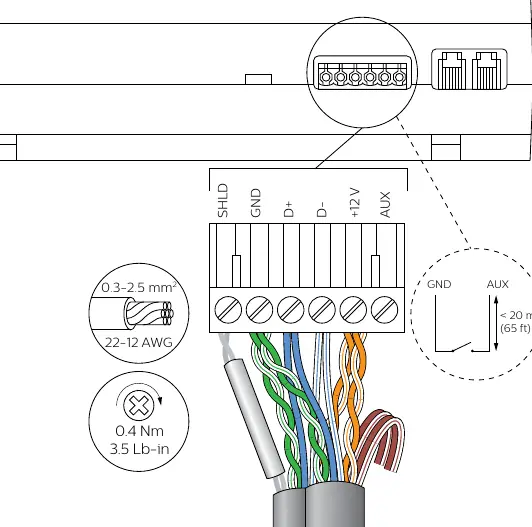
The device utilizes RS-485 DyNet/DMX Rx communication. The communication port layout includes SHLD, GND, D+, D-, +12V, and AUX. The communication power requirement is 12 V at 200 mA (SELV/Class 2). Ensure communication wires are kept separate from high-voltage lines.
Manufacturer information
Philips
Practical help
Common problems
Interference between channels
You must leave a one-channel gap between channels if they are on different phases.
Channel 1 not functioning
Ensure channel 1 is connected to the same phase as the supply terminals.
Before use
- Ensure installation is performed by a qualified electrician.
- Verify the enclosure is approved for electrical equipment.
- Check that supply voltage matches the device ratings.
- Confirm wiring gauge is between 22-12 AWG (0.3-2.5 mm²).
- Verify phase configuration for all channels.
- Ensure proper clearance (45mm) is maintained for ventilation.
Specs in practice
- CH-CH Voltage
- Maximum voltage between channels: 300V (UL) or 400V (CE).
- Inrush Current
- Maximum inrush current capacity is 500A.
- Torque (Power)
- Tighten power terminals to 0.62 Nm (5.5 Lb-in).
- Torque (Comms)
- Tighten communication terminals to 0.4 Nm (3.5 Lb-in).
Images and diagrams
- Wiring diagrams show 1-phase and 3-phase configurations.
- Communication port layout includes SHLD, GND, D+, D-, +12V, and AUX.
Model compatibility
- Compatible with RS-485 DyNet/DMX Rx.
- Requires SELV/Class 2 (UL) power for communication.

Manual page author
Michael Turner
Technical manual editor
Reviews PDF manuals for structure, safety notes, and practical product details so readers can find the right information quickly.