Lighting / Outdoor Lighting
Installation Instructions for RAB Bollard 12/18/24W
A comprehensive installation and wiring guide for the RAB Bollard 12/18/24W. This manual covers anchor bolt installation, standard and 0-10V dimmable wiring, battery backup setup for 24W models, and maintenance procedures.
Table of contents
Manual images
Click an image to enlargeQuick guide from the manual
This document provides installation and maintenance instructions for the RAB Bollard 12/18/24W series. Key requirements include:
- Power: Ensure power is OFF before installation or maintenance.
- Mounting: Must be installed on a level surface, above grade (minimum 1 inch recommended).
- Wiring: Universal voltage driver (120V-277V).
- Battery Backup: Only available for 24W models; requires specific battery connection procedures.
Anchor Bolt and Base Installation
The bollard requires a firm, level surface for mounting. If installing in new concrete, use the provided template to set the anchor bolts.
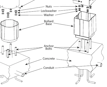
- Install four anchor bolts in the concrete foundation using the provided template. Ensure bolt threads protrude from the concrete.
- Place the Bollard Base over the anchor bolts.
- Loosely tighten the washers, lock washers, and nuts.
- Level the Bollard Base using the provided leveling screws, then tighten all nuts and screws.
- Slide the bollard over the base, aligning it with the grooves, and check the LED position.
- Secure the bollard to the base using the four set screws.
Wiring Instructions
The fixture supports universal voltage (120V-277V, 50/60 Hz). Follow the appropriate diagram based on your configuration:
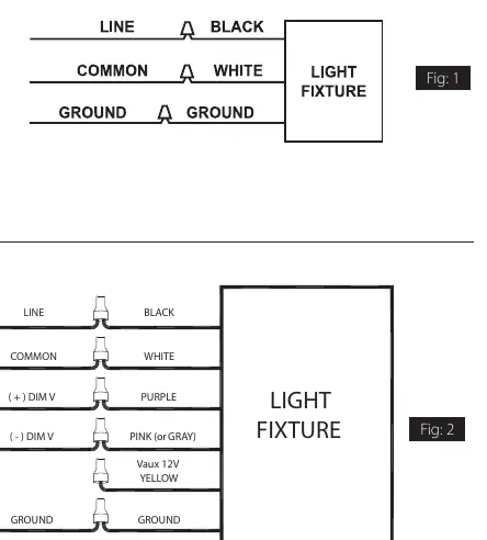
On-Off Wiring
- Connect the black fixture lead to the LINE supply lead.
- Connect the white fixture lead to the COMMON supply lead.
- Connect the GROUND wire from the fixture to the supply ground.
0-10V Dimmable Wiring
- Connect the black fixture lead to the LINE supply lead.
- Connect the white fixture lead to the COMMON supply lead.
- Connect the GROUND wire from the fixture to the supply ground.
- Connect the purple fixture lead to the (V+) DIM lead.
- Connect the pink (or gray) fixture lead to the (V-) DIM lead.
- Cap the yellow fixture lead if present; do not connect.
Battery Backup Models
The battery backup option is exclusive to 24W models. Caution: Voltage can be present in the battery. Do not join the battery connector until installation is complete and AC power is supplied to the emergency driver.
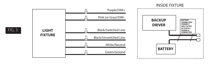
- Wiring: Connect the UNSWITCHED HOT fixture lead to the HOT AC supply line. If using a switched circuit, connect the SWITCHED HOT fixture lead to the external switch.
- Operation: When AC power fails, the fixture automatically switches to emergency mode, operating at reduced illumination for at least 90 minutes.
- Testing: Once the battery has charged for at least one hour, a short test can be performed by pressing the test button. A long duration test (90 minutes) should be performed annually.
Cleaning and Maintenance
Ensure the fixture is cool to the touch before cleaning. Do not clean or maintain while the fixture is energized.
- Clean the lens with a non-abrasive cleaning solution.
- Do not open the fixture to clean the LED.
- Do not touch the LED.
Troubleshooting
- If the fixture is not working, check that the line voltage is correct and the fixture is properly grounded.
- For battery backup models, if the charging indicator light does not illuminate after pressing the test button, verify that the battery is connected properly.
Practical help
Common problems
Charging indicator light does not illuminate
Check if the battery is connected properly inside the fixture.
Fixture not operating
Verify that the line voltage is correct and the fixture is properly grounded.
Before use
- Ensure power is OFF before starting installation.
- Verify the mounting surface is level and at least 1 inch above grade.
- Confirm the branch circuit wiring is available.
- Ensure you have the correct anchor bolts for your specific mounting surface.
- For battery backup models, ensure the battery connector is disconnected until AC power is supplied.
Specs in practice
- Battery Backup
- Available only on 24W models; provides minimum 90 minutes of emergency light.
Images and diagrams
- Fig 1: Standard On-Off wiring connections.
- Fig 2: 0-10V Dimmable wiring connections.
- Fig 3: Battery backup wiring and connector location.
Model compatibility
- Battery backup option is only offered for 24W models.
- Requires UL-approved connectors for wiring.

Manual page author
David Miller
Documentation analyst
Organizes user manual content into clear summaries, with attention to model details, product context, and everyday usability.