Lighting / Fixtures
Installation Guide for Sunco Lighting LED Wall Pack
Quick installation and wiring guide for Sunco Lighting LED Wall Packs. Includes instructions for mounting, 0-10V dimming connections, and field-adjustable wattage and color temperature settings.
Table of contents
Manual images
Click an image to enlargeQuick guide from the manual
This document provides installation and configuration instructions for Sunco Lighting LED Wall Packs. Important: Installation must be performed by a qualified electrician in accordance with the National Electric Code (NEC) and local safety standards. The fixture is designed for wall mounting only and is suitable for wet locations. Ensure power is disconnected before installation or servicing.
Installation
- Open the fixture by removing the two screws on the right side of the housing. If necessary, disconnect the red and black wires at the Wago quick-disconnect to remove the lens door.
- Knock out or drill holes in the rear housing for mounting to the wall and securing to the junction box.
- Apply silicone sealant (not provided) to mounting holes to prevent water entry.
- Secure the fixture to the wall using two or more screws.
- Secure the fixture to the junction box with screws.
- Complete the wiring connections as described below.
- Reinstall the lens door, reconnect the wire leads (red-to-red, black-to-black), and secure with the lens screws.
Wiring Connections
The universal voltage driver operates at 120V to 277V, 50 or 60Hz.
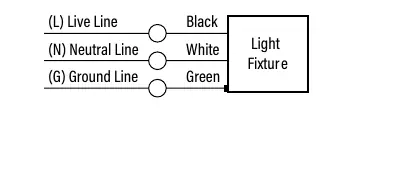
- Standard Wiring: Connect the black fixture line to the (L) Live supply wire, the white fixture line to the (N) Neutral supply wire, and the green fixture line to the (G) Ground supply wire.
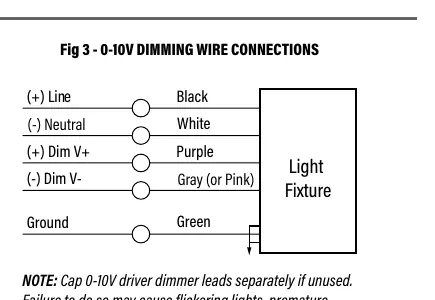
- 0-10V Dimmable Wiring: Connect the black fixture lead to the (+) Line supply, white to the (-) Neutral supply, and green to Ground. Connect the purple fixture lead to the (V+) DIM lead and the gray (or pink) fixture lead to the (V-) DIM lead. Cap the yellow fixture lead if present; do not connect.
Spec-Select Settings
For fixtures with field-adjustable wattage and color temperature (CCT):
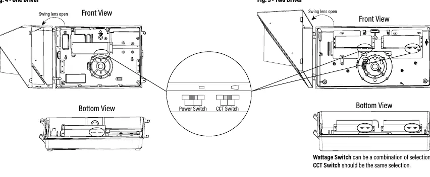
- Open the fixture to locate the slide switches on the bottom of the driver(s).
- Move each switch to the desired position to select from 3 color temperatures (3000K, 4000K, 5000K) and 3 wattage levels.
- For fixtures with two drivers, ensure CCT selections are the same for both drivers. Wattage settings can be mixed.
- Close the fixture and tighten screws after settings are selected.
Maintenance and Troubleshooting
Cleaning: Ensure the fixture is cool before cleaning. Clean the glass lens with a non-abrasive glass cleaning solution. Do not open the fixture to clean the LED and do not touch the LED.
Troubleshooting: If the fixture is not working, verify that the proper line voltage is present, the fixture is wired correctly, and the unit is properly grounded. If using 0-10V dimming, ensure unused leads are capped to prevent flickering or premature failure.
Practical help
Common problems
Flickering lights
Ensure 0-10V driver dimmer leads are capped separately if unused. Failure to do so may cause flickering.
Improper dimming operation
For fixtures with two drivers, ensure DIM lines are connected in parallel with the same polarity (V+ to V+, V- to V-).
Fixture not turning on
Verify that proper line voltage is present, the fixture is wired correctly, and the unit is properly grounded.
Before use
- Ensure power is disconnected before installation or servicing.
- Verify the mounting surface is suitable for wall mounting.
- Confirm the ambient temperature is between -40°C and 40°C.
- Ensure the fixture is mounted in a horizontal position with LEDs facing down.
- Check that the fixture is properly grounded.
Specs in practice
- 0-10V Dimming
- Requires specific wiring (Purple/Gray leads) for dimming functionality.
Images and diagrams
- Fig 1: Back plate showing knock-out template and mounting hole spacing.
- Fig 2: Standard wiring diagram showing Live, Neutral, and Ground connections.
- Fig 3: Wiring diagram for 0-10V dimming applications.
- Fig 4 & 5: Location of wattage and CCT slide switches on the driver.
Model compatibility
- Wall mount only.
- Suitable for wet locations.
- Not for recessed mounting.
- Fixture should be located at least 18 inches below any overhang.

Manual page author
Michael Turner
Technical manual editor
Reviews PDF manuals for structure, safety notes, and practical product details so readers can find the right information quickly.