Lighting / Outdoor Lighting
Installation Guide for Schreder Flaminia Street Light
Quick installation guide for the Schreder Flaminia street light. Includes mounting options, wiring instructions, torque specifications, and safety requirements for 12-24VDC systems.
Table of contents
Manual images
Click an image to enlargeImportant Information
The Schreder Flaminia is a street lighting solution designed for 12-24VDC operation. The control gear must be SELV/PELV compliant with a maximum output voltage (Uout max) of 120V. The unit is rated IP65 and IK06. All tightening torque values specified in this guide are for assemblies without the addition of grease.
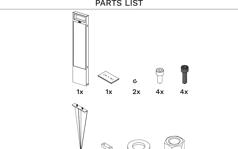
Parts List
Ensure all components are present before beginning installation. The kit includes the main housing, mounting hardware, and necessary fasteners. Refer to the parts diagram on page 1 for a visual inventory of the included items.
Wiring Instructions
Follow the specific sequence for electrical connection to ensure proper operation:
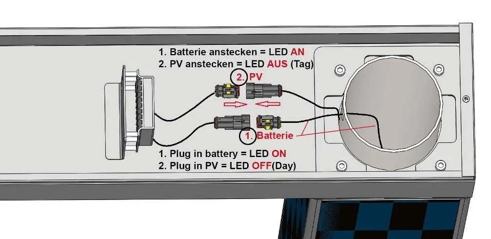
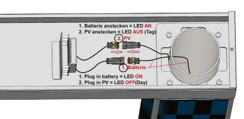
- Connect Battery: Plug in the battery connector first. The LED should turn ON.
- Connect PV: Plug in the PV (photovoltaic) connector. The LED should turn OFF (Day mode).
Installation Steps
The installation requires careful handling of screws. Ensure you use the correct screws as specified in the diagrams. All structural assemblies must be tightened to 15 Nm.
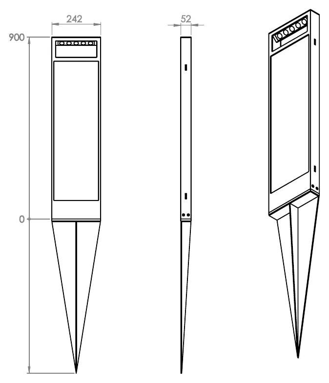
Mounting Options
Option 1: Concrete Foundation
The unit can be mounted using an anchor base. Two sizes are available:
- AS (Anchor Base Small): Dimensions 242mm x 52mm.
- AL (Anchor Base Large): Dimensions 255mm x 150mm.
Option 2: Mounting Wedge
The unit can be installed using a mounting wedge for ground insertion. Ensure the wedge is securely positioned according to the dimensions provided in the technical drawings.
Technical Specifications
- Voltage: 12-24VDC
- Protection Rating: IP65 (Dust tight and protected against water jets), IK06 (Protection against 1 Joule impact)
- Torque: 15 Nm for all assemblies
Practical help
Common problems
LED does not turn on after connecting battery
Ensure the battery connector is fully seated and the battery is charged.
Incorrect torque application
Tighten all assemblies to 15 Nm. Do not use grease on threads as it decreases friction and may affect torque values.
Before use
- Verify the power supply is 12-24VDC.
- Confirm the control gear is SELV/PELV compliant.
- Check that all parts from the parts list are present.
- Ensure the mounting surface (concrete or ground) is prepared according to the chosen option.
Images and diagrams
- Wiring sequence: Connect battery first (LED ON), then connect PV (LED OFF/Day mode).
- Mounting options: Choose between Concrete Foundation (AS/AL) or Mounting Wedge based on site requirements.
Model compatibility
- Requires SELV/PELV control gear.
- Uout max must not exceed 120V.

Manual page author
David Miller
Documentation analyst
Organizes user manual content into clear summaries, with attention to model details, product context, and everyday usability.