Electronics / Cameras
User Manual for RunCam WiFiLink 2 Video System
Quick guide for the RunCam WiFiLink 2 video transmission system. Includes installation, antenna layout, LED status indicators, firmware flashing, PC ground station setup, and OSD troubleshooting.
Table of contents
Manual images
Click an image to enlargeQuick Guide
The RunCam WiFiLink 2 is a video transmission system designed for FPV aircraft. This guide covers the essential setup, including antenna placement, power connection, LED status interpretation, and configuration for both mobile apps and PC ground stations.
Product Features
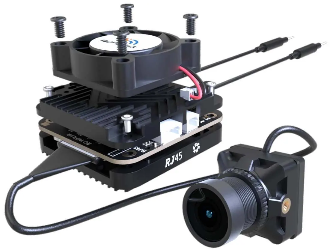
The system consists of the main unit with a cooling fan, M12 lens, and various connectors. Key components include the 6Pin power connector, RJ45 port, and antenna plate. Ensure all screws (M1.68, M1.64, CM1.2) are secure during assembly.
Installation
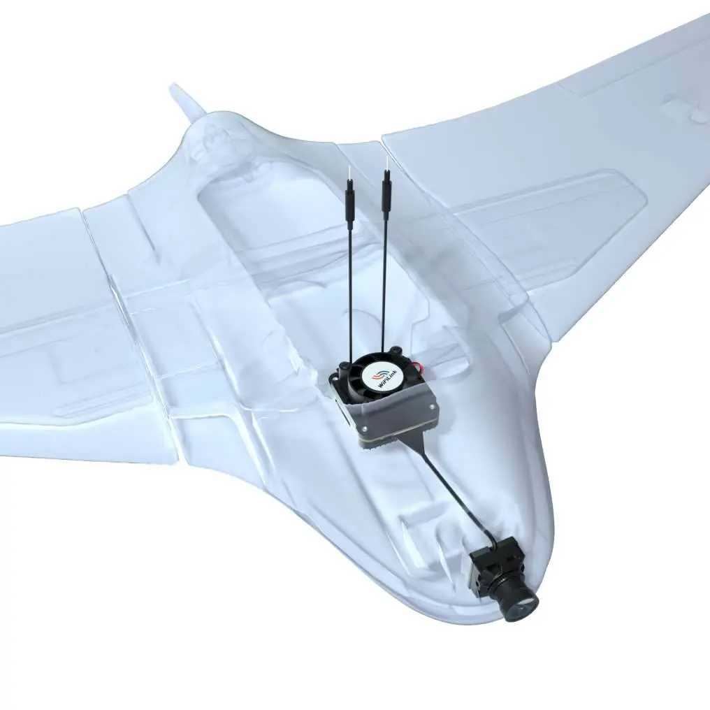
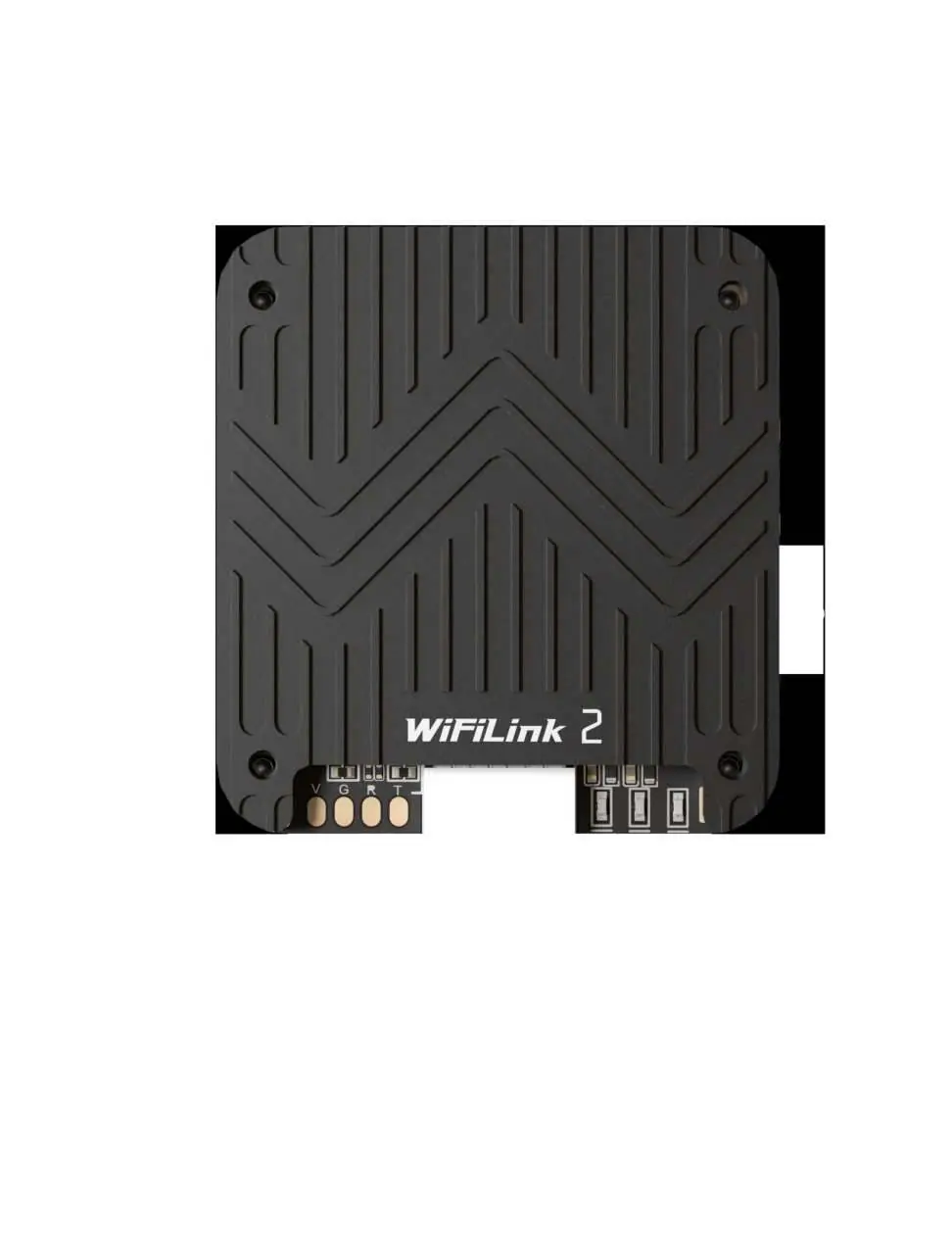
Proper antenna installation is critical for signal performance. Ensure the two tail antennas are fully spread apart to avoid entanglement and reduce signal interference. Point the antennas upward to avoid obstructions from the fuselage or battery. Connect the 6PIN power cable to the flight controller's DJI 6PIN interface, ensuring correct wiring for 9V, GND, RX, and TX.
LED Status Indicators
The system uses LED lights to indicate operational status:

- Green Off: Audio off
- Green Solid: Audio on
- Green Fast Flash: Firmware upgrade
- Green Slow Flash: Recording on
- Blue Solid: Startup
- Blue Fast Flash: WiFi Error
- Blue & Green Alternating Flash: High Temp Warning (>90°C)
Usage and Configuration
To configure the system, download the PixelPilot app. Set the Channel to 161 and the Video Codec to h265. To flash firmware, copy WiFiLink-part0.bin and WiFiLink-part1.bin to the root directory of an empty SD card, insert it into the camera, and power it on. The system will enter upgrade mode automatically.
PC Ground Station Setup
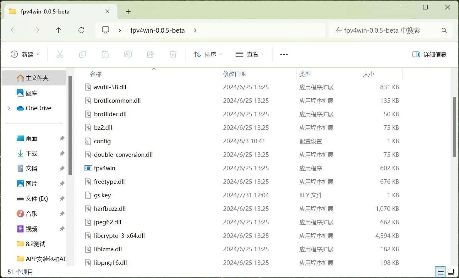
To use with a PC, download the fpv4win program. Insert an 8812AU wireless adapter into your computer and use the Zadig program to reconfigure the driver. Once the driver is set, open fpv4win, select the network card, Channel, and Codec, then click START.
Troubleshooting
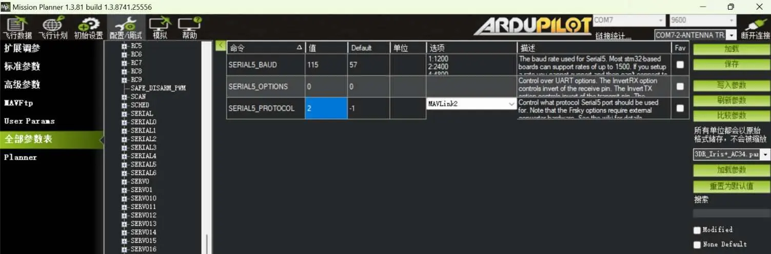
If there is no display, check the power supply and verify that Channel and Codec settings are correct. If FC OSD information is missing, verify that the configuration settings in your flight controller software are correct: set Serial5_Baud to 115 (115200) and Serial5_Protocol to 2 (Mavlink2). Ensure the serial port wiring is correct with TX and RX cross-connected.
Specifications
The system features an IMX415 sensor with a 160° FOV. It supports resolutions up to 1080P@90FPS or 720P@120FPS. The power supply requirement is 9-22V (Max 15W). The unit weighs 30g with the fan or 25g without.
Official resources from the manual
Practical help
Common problems
No display
Check if the power supply is normal (9-22V) and verify that the Channel and Codec settings are correct.
Missing FC OSD information
Verify configuration settings: Serial5_Baud should be 115 (115200), and Serial5_Protocol should be 2 (Mavlink2). Ensure TX and RX are cross-connected.
High Temperature Warning
If the Blue and Green lights are alternating, the unit is overheating (>90°C). Ensure proper airflow.
WiFi Error
If the Blue light is flashing fast, there is a WiFi error. Check your connection and settings.
Before use
- Ensure antennas are fully spread apart.
- Point antennas upward for optimal signal.
- Verify power supply is within 9-22V range.
- Install PixelPilot app or fpv4win software.
- Ensure SD card is empty before firmware flashing.
Specs in practice
- Power Supply
- Input voltage range is 9-22V (Max 15W).
Images and diagrams
- Antenna layout: Ensure antennas are spread apart and pointing upward to avoid signal obstruction.
- 6PIN Connection: Connect the 6PIN power cable to the flight controller's DJI 6PIN interface.
Model compatibility
- Requires 8812AU wireless adapter for PC ground station usage.
- Compatible with flight controllers supporting DJI 6PIN interface.

Manual page author
Emily Carter
User documentation editor
Prepares concise manual descriptions and highlights the most useful setup, operation, and maintenance information for readers.