HVAC / Thermostats & Controls
User Manual for Salus 091FLRFv2 Wireless Thermostat
Quick guide for the Salus 091FLRFv2 wireless thermostat. Includes installation, pairing with RXRT510 receiver, programming, and service menu settings.
Table of contents
Manual images
Click an image to enlargeQuick Guide
The Salus 091FLRFv2 is a wireless weekly programmable thermostat. It comes factory-paired with the RXRT510 receiver. To start, insert 2x AA alkaline batteries into the transmitter. Ensure the receiver is powered (230V) and its switches are set to ON and AUTO. The thermostat allows for heating or cooling control, with customizable temperature programs.
Product Description
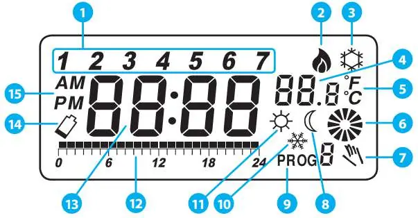
The system consists of a transmitter (thermostat) and a receiver (RXRT510). It is designed for wireless control of heating (e.g., gas boilers, heat pumps) or cooling systems. The thermostat features a large LCD display showing time, temperature, and program status.
Installation
Wall Mounting: Use the provided template to drill two 6mm holes. Insert wall plugs and screws, leaving 3mm of space to hang the thermostat. Slide it to the right to secure it.
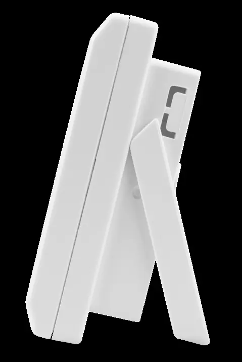
Stand: The thermostat can be used as a free-standing unit by unfolding the rear stand.
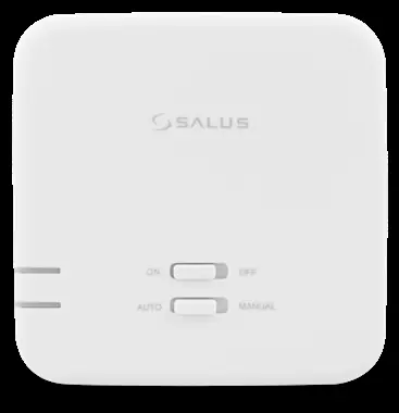
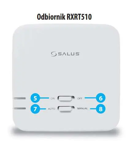
Receiver RXRT510
The receiver must be powered by 230VAC. It features two switches:
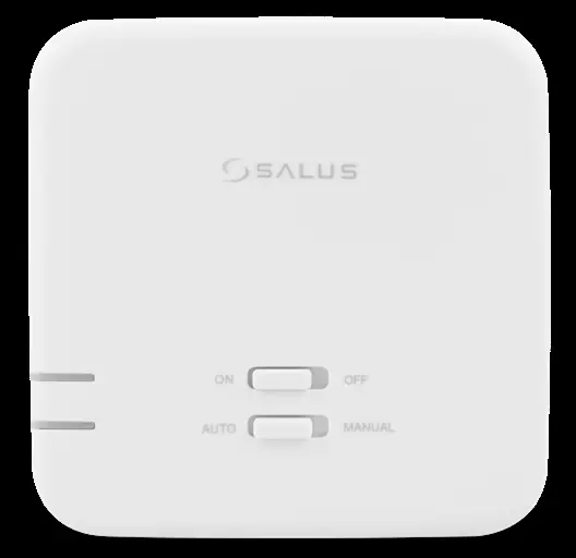
- Top Switch: ON (manual mode active) / OFF (manual mode inactive).
- Bottom Switch: AUTO (receiver follows thermostat signals) / MANUAL (receiver follows top switch position).
LED Indicators: Red LED indicates power and pairing status. Green LED indicates heating signal reception.
Operation
Time Setting: Use buttons D (day), H (hour), and M (minute) after pressing OK to wake the screen.
Temperature Settings: Press the Temp button to set comfort (sun icon) or economic (moon icon) temperatures. Use the sun/moon buttons to adjust values and confirm with OK.
Programming: There are 9 programs (0-5 factory-set, 6-8 user-defined). Use the Prog button to select the day and Prog# to select the program number. You can define custom time blocks for comfort and economic modes.
Service Menu
Access the service menu by holding the OK button for 5 seconds. Use OK to cycle through parameters:
- Heating/Cooling: Select mode.
- Delay: Enable/disable 5-minute start delay.
- Hysteresis: Set to 0.5°C or 1.0°C.
- Offset: Temperature correction (±3.0°C).
- Relay Type: NO (normally open) or NC (normally closed).
- Pairing: SYNC function for pairing with receivers.
Pairing
The device is factory-paired. If re-pairing is needed: Set receiver to AUTO/ON, then toggle the top switch to OFF and back to ON. The red LED will blink. On the thermostat, enter the service menu, select SYNC, and set to ON. Press OK to start the process. The receiver LED will turn solid red when paired.
Troubleshooting
If the receiver LED flashes red, it indicates a loss of signal or low battery in the transmitter. Ensure the transmitter is within range and batteries are fresh. If the system does not respond, perform a factory reset using the small hole next to the OK button (use a paperclip, not a pencil).
Technical Data
Temperature Range: 5-30°C. Hysteresis: 0.5°C or 1.0°C. Power: 2x AA batteries (transmitter), 230V AC (receiver). Frequency: 868MHz. Max Load: 16A (resistive), 5A (inductive).
Manufacturer information
SALUS Controls
Practical help
Common problems
Receiver LED flashing red
Indicates loss of signal or low battery. Check transmitter batteries and distance/interference.
Heating not turning on
Verify receiver switches are set to ON and AUTO. Check wiring connections.
Pairing fails
Ensure receiver is in pairing mode (blinking red LED) before starting SYNC on the thermostat.
Before use
- Insert 2x AA alkaline batteries into the thermostat.
- Ensure the receiver is connected to 230V power.
- Set receiver switches to ON and AUTO positions.
- Mount the thermostat 1.5m above floor level, away from heat sources or drafts.
Specs in practice
- Frost Protection
- A fixed 7°C setting to prevent pipes from freezing during long absences.
Images and diagrams
- Wiring diagram shows L/N power input and COM/NO relay output for boiler connection.
- Receiver switches: Top switch controls manual ON/OFF; bottom switch toggles between AUTO and MANUAL modes.
Model compatibility
- Compatible with RXRT510 receiver, SPE868 plug, and SR868 relay.

Manual page author
Emily Carter
User documentation editor
Prepares concise manual descriptions and highlights the most useful setup, operation, and maintenance information for readers.