HVAC / Thermostats & Controls
User Manual for Salus 091FLv2 Digital Programmable Thermostat
Quick guide for the Salus 091FLv2 and 091FLRFv2 digital programmable thermostat. Learn how to set up, program, wire, and configure service settings for heating and cooling control.
Table of contents
Manual images
Click an image to enlargeQuick guide from the manual
The Salus 091FLv2 (wired) and 091FLRFv2 (wireless) are weekly programmable thermostats designed to control room temperature in heating or cooling systems. The device uses 2x AA 1.5V alkaline batteries. The wireless version (091FLRFv2) comes pre-paired from the factory. Ensure the device is installed by a qualified person in accordance with local regulations.
Installation and Wiring
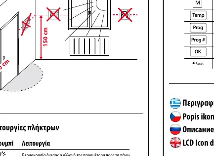
Proper placement is essential for accurate temperature reading. Install the thermostat at a height of approximately 150 cm and at least 20 cm away from walls. Avoid placing it near heat sources or in direct sunlight.
Wiring:
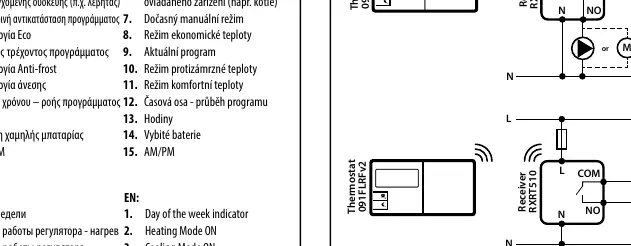
- 091FLv2 (Wired): Connect the COM and NO terminals to your heating/cooling device.
- 091FLRFv2 (Wireless): The receiver (RXRT510) connects to the power supply (230V AC) and the heating device. The thermostat communicates wirelessly with the receiver.
Operation and Settings
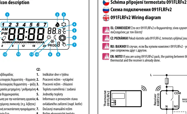
Setting Time: Press the D button to set the day, H for the hour, and M for the minutes.
Setting Temperatures:
- Comfort Temperature: Press the Sun icon button to view/change the comfort temperature.
- Economic Temperature: Press the Moon icon button to view/change the economic temperature.
Programming:
- There are 9 programs available. Programs 0-5 are factory-set. Programs 6-8 are user-definable.
- To set a program, press the Prog button, select the day, and choose the program number (0-8). Use the arrow buttons to assign comfort or economic temperature for each hour of the day.
Service Menu
To access the service menu, press the backlight button to wake the screen, then hold the Moon icon button for 5 seconds. Use the arrow buttons to navigate and the OK button to confirm settings:
- Heating/Cooling Mode: Select between heating (relay closes on demand) or cooling (relay closes with 5-minute delay).
- Delay Switch: Enable or disable the 5-minute delay for the heating device.
- Pairing (RF only): Used to re-pair the thermostat with the receiver.
- Hysteresis: Select between 0.5°C or 1.0°C.
- Temperature Correction: Adjust the measured temperature by -3.0°C to +3.0°C.
- Output Type: Configure as Normally Open (NO) or Normally Closed (NC).
Troubleshooting and Pairing
If you need to re-pair the 091FLRFv2 thermostat with the receiver: Ensure the receiver is disconnected from power and switches are set to AUTO and ON. Connect power to the receiver and wait for the red LED to light steadily. Switch the receiver to OFF and then quickly back to ON. The red LED will flash, indicating pairing mode. Press the OK button on the thermostat to begin the process.
Manufacturer information
SALUS Controls
Practical help
Common problems
Wireless thermostat not communicating with receiver
Perform the re-pairing process: Set receiver to AUTO/ON, power cycle, then switch OFF/ON quickly to enter pairing mode, and confirm on the thermostat.
Temperature reading is inaccurate
Use the Service Menu to adjust the 'Temperature Correction' setting within the range of -3.0°C to +3.0°C.
Relay not activating
Check if the device is in the correct mode (Heating vs Cooling) and verify the wiring connections (NO/COM).
Before use
- Insert 2x AA 1.5V alkaline batteries (do not use rechargeable).
- Ensure the thermostat is placed 150cm above the floor and 20cm from walls.
- Verify if you have the wired (091FLv2) or wireless (091FLRFv2) version.
- For wireless models, ensure the receiver is connected to 230V AC power.
- Set the current day and time before programming.
Images and diagrams
- Wiring diagrams show how to connect the COM and NO terminals to the heating/cooling device.
- The receiver diagram for 091FLRFv2 shows the connection to 230V AC power and the output relay.
Model compatibility
- 091FLRFv2 comes pre-paired from the factory.
- Output type (NO/NC) configuration is available from software version 2.6.

Manual page author
Michael Turner
Technical manual editor
Reviews PDF manuals for structure, safety notes, and practical product details so readers can find the right information quickly.