Industrial / Access Control
User Manual for FAAC 170CLAVEASY Access Control Keypad
Quick guide for the FAAC 170CLAVEASY access control keypad. Learn how to install, wire, program master codes, add users, and configure relay settings.
Quick answers from the manual
Quick answer
- The FAAC 170CLAVEASY is an access control keypad. Programming is accessed via a master code (default 1234). It supports proximity cards and codes with 3 operating modes. p. 1, 2
Key actions
- Enter programming mode p. 2
- Reset master code p. 3
First start
- Enter programming mode using the default master code 1234. p. 2
Problems and fixes
Keypad blocked
Wait 60 seconds after 5 incorrect attempts.
p. 4Maintenance and reset
- Reset to factory settings p. 3
Technical specifications
| Parameter | Value | Meaning | Pages |
|---|---|---|---|
| Power Supply | 12-24 VAC/VDC | Operating voltage | p. 1 |
| IP Rating | IP65 | Ingress protection | p. 1 |
Where to find it in the PDF
- Technical Specifications and Mounting p. 1
- Wiring Diagram and Basic Programming p. 2
- Advanced Programming p. 3, 4, 5
Table of contents
Manual images
Click an image to enlargeQuick guide from the manual
The FAAC 170CLAVEASY is an access control keypad designed for secure entry. This manual provides instructions for installation, wiring, and programming. The device supports proximity cards and codes, with three operating modes: autonomous proximity reader, proximity reader or code, and proximity reader and code.
Technical Specifications
- Power Supply: 12-24 VAC or VDC (+/- 10%), Max 30V
- Consumption: ≤ 80 mA (active), ≤ 110 mA (standby)
- Relays: 2 outputs (30V AC/DC - 1A)
- User Capacity: Relay 1 = 1000 users, Relay 2 = 10 users
- Frequency: EM 125KHz
- Operating Temperature: -20°C to +50°C
- Protection Rating: IP65
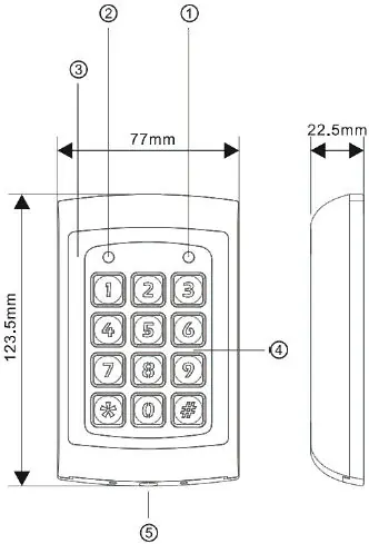
- Dimensions: 123.5 x 77 x 22.5 mm
Installation and Wiring
Installation must be performed by qualified personnel. Ensure the device is not installed in explosive environments or areas with high electromagnetic interference.
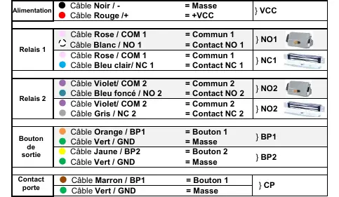
Wiring Connections:
- Power: Black (GND/-), Red (+VCC)
- Relay 1: Pink (COM1), White (NO1), Light Blue (NC1)
- Relay 2: Violet (COM2), Dark Blue (NO2), Grey (NC2)
- Exit Buttons: Orange (BP1/GND), Yellow (BP2/GND)
- Door Contact: Brown (CP/GND)
Programming
To enter programming mode, enter the master code twice (Factory default: 1234). To exit, press the # button. The device automatically exits programming mode after 30 seconds of inactivity.
Changing the Master Code
- Enter programming mode.
- Press * 3.
- Enter the new 4-digit master code twice.
Adding Users
Users can be added for Relay 1 (001-999) or Relay 2 (00-09). Select the desired mode (Card only, Card or Code, Card and Code) using the specific menu codes provided in the full manual, then enter the memory slot number (001-999) and present the card or enter the code.
Safety and Maintenance
The device must be installed in a cabinet not accessible to the operator. Use only original spare parts for repairs. In case of maintenance or cleaning, disconnect the power supply. The master code cannot unlock the door. After 5 incorrect entry attempts, the keypad will lock for 60 seconds.
Practical help
Common problems
Keypad locked
The keypad locks for 60 seconds after 5 incorrect entry attempts.
Forgot master code
Cut power to the keypad. Press and hold the # button while restoring power until a beep is heard to reset to factory default (1234).
Before use
- Verify power supply is 12-24 VAC/VDC.
- Ensure installation is performed by qualified personnel.
- Check that the environment is not explosive or subject to high electromagnetic interference.
- Ensure all wiring connections match the provided diagram.
Images and diagrams
- Wiring diagram shows connections for power (VCC), two relays (NO/NC), exit buttons (BP1/BP2), and door contact (CP).
Model compatibility
- Supports EM 125KHz proximity cards.
- Relay 1 supports up to 1000 users.
- Relay 2 supports up to 10 users.

Manual page author
David Miller
Documentation analyst
Organizes user manual content into clear summaries, with attention to model details, product context, and everyday usability.