Power / Uninterruptible Power Supplies
Electric Drop Bolt Lock Visionis VIS-DP100-FSA User Manual
Quick guide for the Visionis VIS-DP100-FSA electric drop bolt lock. Includes installation steps, wiring definitions, technical specifications, and hole dimensions.
Quick answers from the manual
Quick answer
- The VIS-DP100-FSA is a fail-safe electric drop bolt lock. It requires a 12V-24V DC power supply and a hole cut into the door frame (207mm x 36mm, depth >= 38mm). p. 1, 2
Key actions
- Cut a hole in the door frame p. 2
- Connect wires according to definitions p. 2
First start
- Mount the lock body on the door frame and test p. 3
Technical specifications
| Parameter | Value | Meaning | Pages |
|---|---|---|---|
| Voltage | DC 12V - 24V | Operating power | p. 1 |
| Holding Force | 800Kg (1700lbs) | Strength of the lock | p. 1 |
Where to find it in the PDF
- Dimensions and Features p. 1
- Installation and Wiring p. 2
- Installation Steps p. 3
Table of contents
Manual images
Click an image to enlargeImportant information from the manual
The Visionis VIS-DP100-FSA is a fail-safe electric drop bolt lock designed for secure access control. This device requires professional installation if you are not experienced with electrical equipment. Always check with your local Fire authority to ensure compliance with local Fire Codes before installation.
Technical specifications
- Voltage: DC 12V - 24V
- Holding Force: 800Kg (1700lbs)
- Current (DC12V): Start 1A, standby 0.11A
- Function: Fail Safe (N/C with power it locks)
- Time Delay: 0, 3, 6 seconds
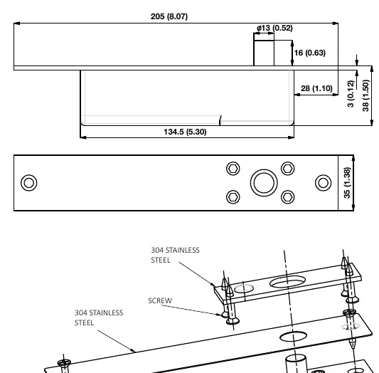
- Bolt Diameter: 13mm stainless steel (16mm throw)
- Operating Temperature: -20°C to +50°C (-4°F to 122°F)
- Dimensions: 205mm(L) x 35mm(W) x 38mm(H)
Installation
The installation requires cutting a hole in the door frame. Ensure the depth of the hole is not less than 38mm.
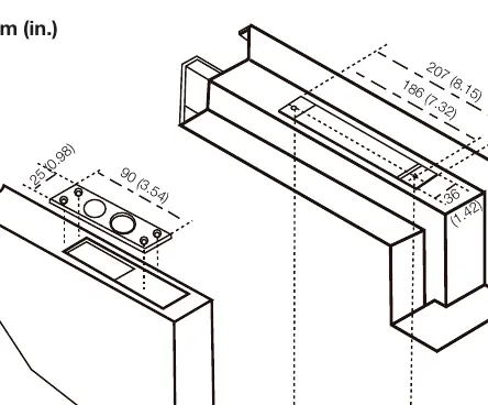
- Hole Size: 207mm(L) x 36mm(W)
- Decorative Plate Size: 215mm(L) x 41mm(W) x 0.6mm(H)
- Lock Face Plate Size: 205mm(L) x 35mm(W) x 3mm(H)
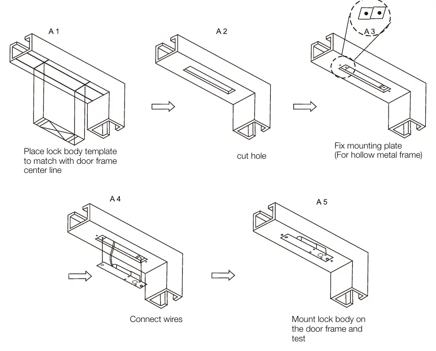
Installation Steps:
- Place the lock body template to match the door frame center line.
- Cut the hole according to the template.
- Fix the mounting plate (for hollow metal frames).
- Connect the wires.
- Mount the lock body on the door frame and test the operation.
Wiring definitions
Connect the wires according to the following definitions:
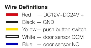
- Red: DC12V ~ DC24V +
- Black: GND
- Yellow: Push button switch
- White: Door sensor COM
- Blue: Door sensor NO
Practical help
Common problems
Lock does not engage
Verify the power supply is providing 12V-24V DC and check all wiring connections against the definitions.
Hole size is incorrect
Ensure the hole cut is at least 207mm x 36mm with a minimum depth of 38mm.
Before use
- Verify power supply is 12V-24V DC
- Ensure door frame can accommodate a 38mm deep hole
- Check local fire codes for compliance
- Confirm the door type (Standard, Narrow, Frameless glass)
Images and diagrams
- The wiring diagram defines the color-coded connections for power, push button, and door sensors.
- Installation diagrams illustrate the template alignment, hole cutting, and mounting process for different door types.
Model compatibility
- Suitable for various door types including Standard, Narrow, and Frameless glass doors.

Manual page author
Michael Turner
Technical manual editor
Reviews PDF manuals for structure, safety notes, and practical product details so readers can find the right information quickly.