Industrial / Access Control
SDC 2090AH Failsecure Heavy Duty Concealed Mortise Bolt Lock Installation Guide
Comprehensive installation and wiring guide for the SDC 2090AH Failsecure Heavy Duty Concealed Mortise Bolt Lock. Includes detailed mounting instructions for horizontal and vertical applications, wiring diagrams for AC and DC operation...
Quick answers from the manual
Quick answer
- The SDC 2090AH is a concealed mortise bolt lock. Installation involves cutting a 1-1/2" x 8" mortise in the door frame, mounting the tabs, wiring the solenoid, and securing the lock. The Auto Relock Switch can be adjusted for door gaps greater than 1/8". p. 1
Key actions
- Adjusting the Auto Relock Switch (ARS) p. 1
- Wiring the lock p. 2
Problems and fixes
Bolt will not retract
Check voltage and alignment of strike.
p. 2
Bolt does not project
Strike is mis-aligned.
p. 2Technical specifications
| Parameter | Value | Meaning | Pages |
|---|---|---|---|
| Face plate | 8" x 1-1/2" x 1/8" | Physical dimensions of the face plate. | p. 2, 3 |
| Bolt | 3/4" dia. stainless steel, 3/4" throw | Bolt material and throw distance. | p. 2, 3 |
| Solenoid | Continuous duty, fail secure | Operational type of the solenoid. | p. 2 |
Where to find it in the PDF
- Installation Instructions p. 1
- Wiring and Specifications p. 2
- Dimensions and Preparation p. 3
Table of contents
Manual images
Click an image to enlargeImportant Information
The SDC 2090AH is a failsecure, heavy-duty concealed mortise bolt lock designed for existing entrances. Proper installation requires precise mortising of the door and frame. Key operational features include an adjustable Auto Relock Switch (ARS) to compensate for door gaps and optional sensors for bolt and door position monitoring.
Installation Instructions
The lock can be installed in either horizontal (overhead) or vertical (side jamb) configurations.
Horizontal Installation (Overhead)
- Examine the top rail of the door to locate the strike position.
- Mark the door for the end of the strike closest to the lock stile and make a corresponding mark on the header.
- Locate the centerline of the door thickness on the header and attach the adhesive cut-out template.
- Center punch the tab-mounting screw locations, counter-sink for #10 screws, and saw or rout out the cut-out area.
Vertical Installation (Side Jamb)
- Examine the lock stile jamb for the center of the door height.
- Mark the door stile horizontal for the top end of the strike and make a corresponding mark on the jamb.
- Attach the cut-out template to the jamb, aligning the top of the cut-out with the horizontal mark.
- Center punch the tab mounting screw locations, counter-sink for #10 screws, and saw or rout out the 1-1/2" x 8" cut-out.
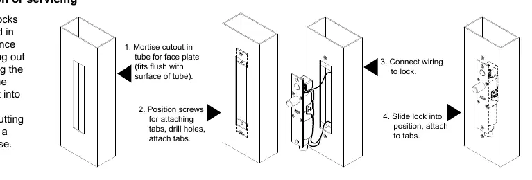
Final Mounting
- Attach the mounting tabs inside the frame.
- Connect power supply leads to the lock leads. Handle the lock carefully; do not hang it by the wire leads.
- Insert the lock into the cut-out. Ensure the bolt end is nearest the lock stile (horizontally) or at the top end of the cut-out (vertically).
- Secure the lock with #10-32 machine screws.
- Use the strike as a template to mark and drill screw holes, then attach the strike.
Auto Relock Switch (ARS) Adjustment
The ARS is factory-set for 1/8" clearance between the top of the door and the transom bar or head jamb. If there is a wider gap, you can compensate:
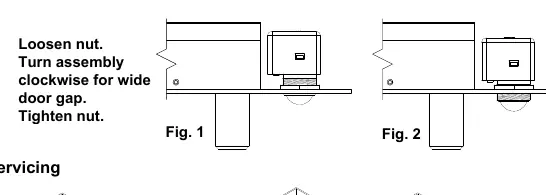
- Loosen the lock nut.
- Turn the assembly clockwise to adjust for a wider door gap.
- Tighten the lock nut securely once the adjustment is satisfactory.
Wiring Information
The lock supports both DC and AC operation. Ensure the power supply matches the requirements.
- DC Operation: Connect the access control/key switch/push button (N/O) to the solenoid. Ensure correct polarity for the 24VDC power input.
- AC Operation: Requires a rectifier and transformer (115V/24VAC, 92VA min).
Troubleshooting
- Bolt will not retract: Check the voltage and the alignment of the strike.
- Bolt does not project: The strike is likely misaligned.
Practical help
Common problems
Bolt will not retract
Check the power supply voltage and ensure the strike is properly aligned with the bolt.
Bolt does not project
The strike is likely misaligned; adjust the strike position.
Before use
- Verify the door frame has sufficient space for the lock and strike.
- Ensure the power supply is 24VDC (or 115VAC with transformer/rectifier for AC operation).
- Confirm the mortise cut-out dimensions match the template (1-1/2" x 8").
- Check that the Auto Relock Switch (ARS) is adjusted for your specific door gap.
- Ensure the lock is not hanging by the wire leads during installation.
Images and diagrams
- The ARS adjustment diagram shows how to loosen the nut and turn the assembly clockwise to accommodate wider door gaps.
- The installation steps diagram illustrates the sequence: mortise cutout, position tabs, connect wiring, and slide lock into position.
- Wiring diagrams provide specific connections for DC and AC power sources, including N/O and N/C configurations.
Model compatibility
- Optional Bolt Position Sensor (BPS) indicates bolt locked or unlocked (0.25 amp).
- Optional Door Position Switch (DPS) indicates door open or closed (5A @ 125VAC Resistive).

Manual page author
Michael Turner
Technical manual editor
Reviews PDF manuals for structure, safety notes, and practical product details so readers can find the right information quickly.