Industrial / Access Control
Security Brands Advantage DKLP Economy Keypad 19-100E Quick Start Guide
Quick start guide for the Security Brands Advantage DKLP Economy Keypad (19-100E). Includes installation steps, wiring diagrams for gate operators and locks, programming instructions, and master reset procedures.
Quick answers from the manual
Quick answer
- The Advantage DKLP Economy (19-100E) is a keypad for gate operators and door strikes. It requires 7-14 VDC power and is programmed using a Master Code (default 1251). p. 1
Key actions
- Add Access Code p. 3
- Change Master Code p. 3
First start
- Mount the unit, connect 7-14 VDC power, and program access codes using the default Master Code 1251. p. 1, 3
Problems and fixes
Forgot Master Code
Perform Master Reset Procedure: disconnect power, hold Reset Button, reconnect power, release button.
p. 4Maintenance and reset
- Master Reset Procedure resets the Master Code to 1251. p. 4
Technical specifications
| Parameter | Value | Meaning | Pages |
|---|---|---|---|
| Power | 7-14 VDC | Operating voltage range | p. 1, 2 |
Where to find it in the PDF
- Installation and Wiring p. 1, 2
- Programming p. 3, 4
Table of contents
Manual images
Click an image to enlargeQuick guide from the manual
The Advantage DKLP Economy (19-100E) is a keypad designed for gate operators and door strikes. This guide covers the installation, wiring, and programming of the unit. The default Master Code is 1251. Always ensure the gate path is clear before operating.
Installation
Mounting:
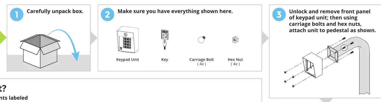
- Carefully unpack the box and verify all components (Keypad Unit, Key, 4x Carriage Bolts, 4x Hex Nuts).
- Unlock and remove the front panel of the keypad unit.
- Attach the unit to the pedestal using the provided carriage bolts and hex nuts.
- Insert the front panel into the enclosure for ease of wiring.
Wiring
Power Requirements: The unit requires 7-14 VDC power. Ensure correct polarity (positive to positive, negative to negative) to avoid damage.
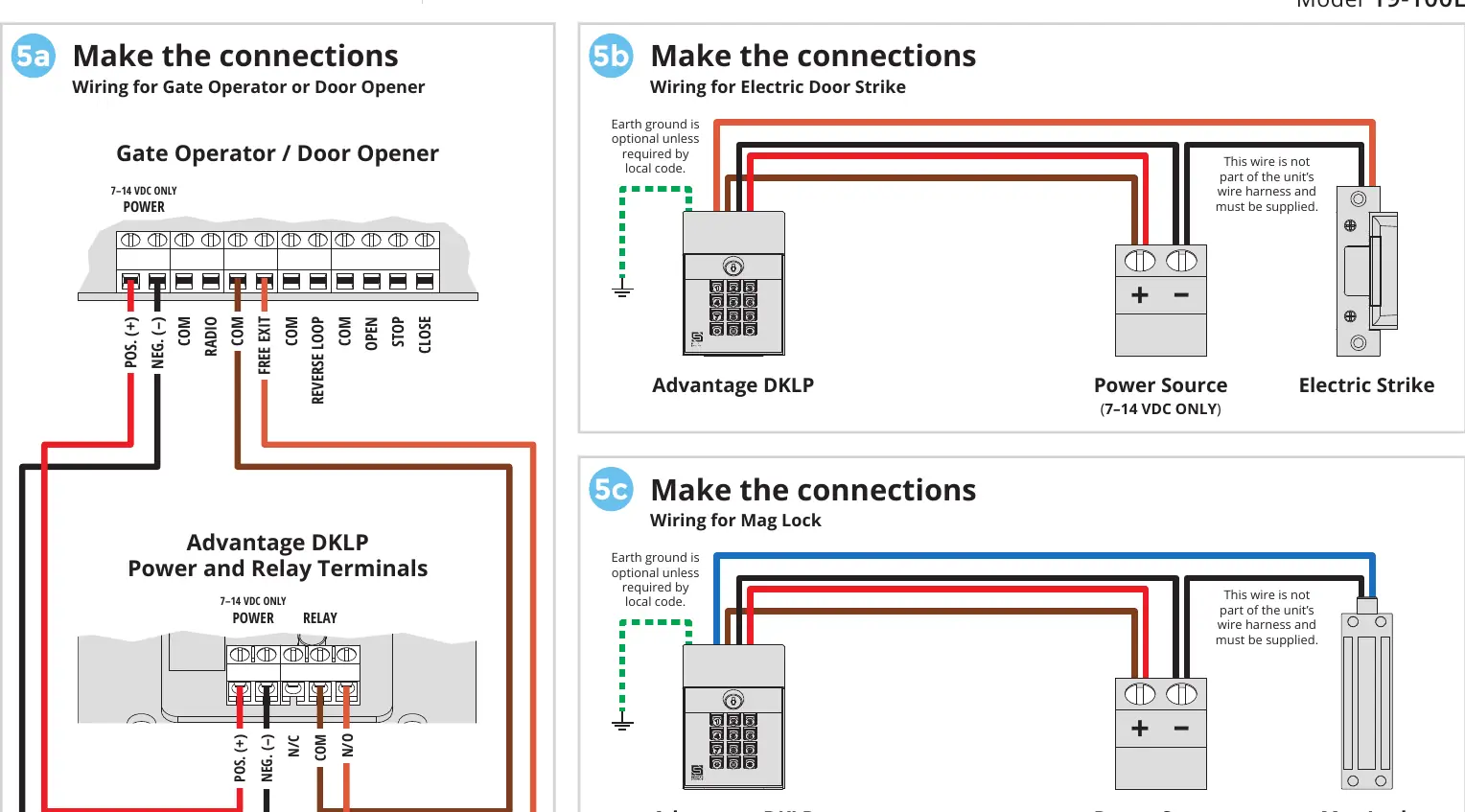
Connection Types:
- Gate Operator / Door Opener: Connect to the Power and Relay Terminals as shown in the wiring diagram.
- Electric Door Strike: Connect the keypad to the power source and the electric strike. Earth ground is optional unless required by local code.
- Mag Lock: Connect the keypad to the power source and the mag lock.
Programming
All programming is performed using the Master Code (default 1251). The green arrow indicates a "good" tone; an incorrect entry will sound a "bad" tone.
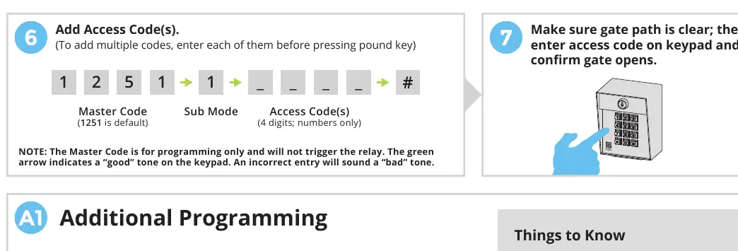
- Add Access Code(s): 1251 -> 1 -> [4-digit code] -> #
- Delete Code(s): 1251 -> 2 -> [4-digit code] -> #
- Change Master Code: 1251 -> 3 -> [New 4-digit code] -> #
- Set Latch Code: 1251 -> 5 -> [4-digit code] -> #
- Set Relay Output Time: 1251 -> 4 -> [0-9 seconds] -> #
- Delete All Codes: 1251 -> 0 -> 1251 -> #
Important Keys:
- Star Key (*): Deletes your current entry if you make a mistake.
- Pound Key (#): Exits Programming Mode.
Master Reset Procedure
Use this procedure if the Master Code or Latch Code is forgotten.
- Open the front panel.
- Disconnect power by removing one power wire from the screw terminal.
- Press and hold the Reset Button.
- Reconnect power while holding the button, then release the Reset Button after hearing a tone.
- Close the front panel. The Master Code is now reset to 1251.
Manufacturer information
Security Brands, Inc.
Practical help
Common problems
Forgot Master Code or Latch Code
Perform the Master Reset Procedure (disconnect power, hold reset button, reconnect power).
Made a mistake while entering a code
Press the star key (*) to delete the current entry and start over.
Keypad not responding or error tone
Check power polarity (7-14 VDC) and ensure you are waiting for the 'good' tone before proceeding.
Before use
- Ensure power source is 7-14 VDC.
- Verify gate path is clear.
- Check wiring polarity (positive to positive, negative to negative).
- Ensure you have the default Master Code (1251).
Images and diagrams
- Wiring diagrams illustrate connections for Gate Operators, Electric Strikes, and Mag Locks.
- The front panel diagram identifies the Power and Relay Terminals and the Reset Button.
Model compatibility
- Compatible with gate operators, electric strikes, and mag locks.
- Requires 7-14 VDC power supply.

Manual page author
Michael Turner
Technical manual editor
Reviews PDF manuals for structure, safety notes, and practical product details so readers can find the right information quickly.