Tools / Tool Storage
Sealey APR3001 Heavy-Duty 3 Beam Set Racking Unit User Manual
Quick guide for the Sealey APR3001 Heavy-Duty 3 Beam Set Racking Unit. Includes assembly instructions, safety warnings, specifications, and component list.
Table of contents
Manual images
Click an image to enlargeQuick guide from the manual
The Sealey APR3001 is a heavy-duty racking unit designed for direct loading of small storage pallets. It features a capacity of 1000kg per level. Assembly requires two people and should be performed on a level, solid surface such as concrete. Always ensure the unit is properly assembled and secured before loading.
Safety Instructions
- Surface: Erect the racking on a level and solid surface, such as concrete.
- Environment: Do not use outdoors, in damp/wet locations, or areas with condensation.
- Usage: Do not use for any purpose other than designed. Do not clean cross beams with solvents.
- Stability: Where possible, fix the unit to the wall with suitable fixings.
- Loading: Maximum load is 1000kg per shelf. Load must be evenly distributed. Place heavier items on lower racks.
- Maintenance: Ensure all clips are locked securely and safety bolts are fitted before use.
Specifications
- Model No: APR3001
- Overall Size: 2250 x 1000 x 2000mm
- Capacity: 3000kg total (1000kg per level)
- Beam Width: 2250mm
Contents
Before assembly, unpack and check the following parts:
- A: Upright (Qty 4)
- B: Horizontal Brace (Qty 4)
- C: Diagonal Brace (Qty 6)
- D: Spacer (Qty 4)
- F: Bolt M6 x 45mm (Qty 12)
- G: Nut M6 (Qty 12)
- H: Locking Pin (Qty 12)
- I: Cross Beam (Qty 6)
Assembly
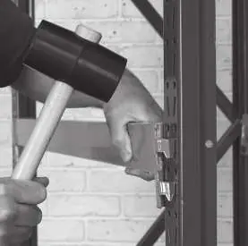
It is recommended that this system be assembled by two people. Use a rubber mallet for installation; do not use a hard-faced hammer as it will damage the surface finish.
Assembling the End Frames
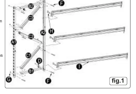
- Place uprights (A1 & A2) on the floor with inner edges facing each other.
- Insert horizontal brace (B1) and spacer (D) into upright (A2) at the base hole; secure loosely with bolt (F) and nut (G).
- Align upright (A1) with brace (B1) and diagonal brace (C1); secure loosely.
- Continue attaching diagonal braces (C1, C2, C3) and horizontal braces (B2) to uprights using bolts (F) and nuts (G) as detailed in the assembly diagram.
- Check that the frame is square and tighten all fasteners. Repeat for the second frame.
Fitting the Cross Beams
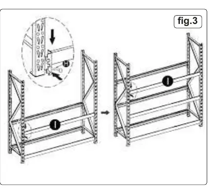
- Support one end frame vertically. Attach the end of one cross beam (I) to the base of an upright (A).
- Ensure tags on the end bracket engage properly with the slots in the upright.
- Tap the cross beam gently with a rubber mallet to seat it properly.
- Insert the locking pin (H) to secure the beam.
- Connect the other end of the beam to the second end frame at the same height and secure with a locking pin (H).
- Repeat for additional cross beams at required heights. Ensure all tabs are fully engaged and beams are tapped down before securing with locking pins.
Manufacturer information
Sealey Group
Practical help
Common problems
Cross beam not seating properly in slots
Ensure tags on the end bracket engage properly with the slots. Tap the beam gently next to the end bracket with a rubber mallet.
Frame feels unstable during assembly
Check that the assembled frame is square before tightening all fasteners.
Surface damage on cross beams
Do not use a hard-faced hammer. Use a rubber mallet only.
Before use
- Ensure the racking is on a level, solid surface (concrete).
- Verify all clips are locked securely in place.
- Ensure all safety bolts are fitted.
- Confirm the load is evenly distributed across the racks.
- Check that heavier items are placed on the lower racks.
- Ensure the unit is fixed to the wall if possible.
Specs in practice
- Capacity per level
- 1000kg maximum load per shelf level.
- Total Capacity
- 3000kg maximum load for the entire unit.
- Overall Size
- 2250 x 1000 x 2000mm (Width x Depth x Height).
Images and diagrams
- Fig 1: Detailed view of end frame assembly showing uprights, braces, and spacers.
- Fig 2: Close-up of cross beam bracket engagement and locking pin insertion.
- Fig 3: Overview of the completed racking unit assembly.
Model compatibility
- Designed for direct loading of small storage pallets.
- Extra components are available to create additional storage racks.

Manual page author
David Miller
Documentation analyst
Organizes user manual content into clear summaries, with attention to model details, product context, and everyday usability.