HVAC / Heaters & Fireplaces
Sealey Space Warmer Kerosene/Diesel Heater AB350, AB708.V3, AB7081.V3 User Manual
Quick guide for Sealey Space Warmer Kerosene/Diesel heaters (AB350, AB708.V3, AB7081.V3). Includes assembly, operation, maintenance, and troubleshooting steps.
Table of contents
Manual images
Click an image to enlargeQuick guide from the manual
This manual covers the operation and maintenance of Sealey Space Warmer heaters. These units are designed for use with kerosene or diesel fuel in well-ventilated areas. Important: Never use bio-diesel. Ensure the heater is placed on a flat, non-flammable surface and that there is adequate ventilation (minimum 250 cm² opening) to prevent carbon monoxide poisoning. Always allow the cooling sequence to complete before unplugging the unit.
Assembly
For model AB7081.V3, follow these assembly steps:
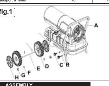
- Insert the wheel shaft (E) into the caster fixing plate (J).
- Secure the shaft using the cotter pin (I).
- Fit plain washers (F) on both sides of the shaft, then slide the wheels (D) onto the shaft.
- Secure the wheels with the nut (G) and install the wheel covers (H).
- Attach the handle (A) to the caster fixing plate using the clamping screws (C) and plain washers (B).
Operation
Start-up
- Fill the tank with clean kerosene or diesel. Check the fuel gauge on top of the tank.
- Connect the power cord to a 230V~50Hz earthed electrical supply.
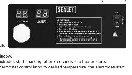
- Push the power switch to the ON (I) position.
- The left display shows the default temperature (20°C). If the ambient temperature is lower, the heater will start after 7 seconds. If higher, adjust the thermostat knob to the desired temperature.
Shut Down
Move the switch to the OFF (O) position. Never disconnect the heater from the mains while it is in operation; always allow the cooling sequence to complete to prevent damage to internal components.
Maintenance
Maintenance should be performed by qualified personnel only.
- Nozzle: Unscrew the nozzle, blow compressed air through the orifice to clean, and replace if necessary.
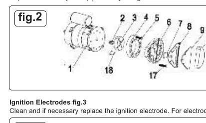
- Air Filters: Remove the filter end cover, wash the air intake filter with light detergent, and dry thoroughly. Replace the air delivery filter once a year.
- Ignition Electrodes: Clean and replace if necessary. Ensure the gap is set to 3.1mm.
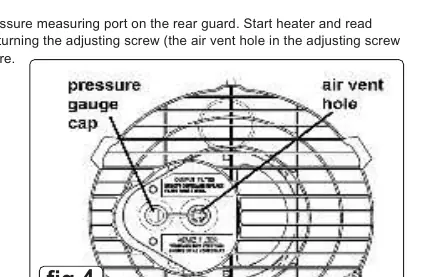
- Compressor Pressure: Factory set. If adjustment is required, connect a pressure gauge to the rear port and turn the adjusting screw clockwise to increase or anticlockwise to decrease pressure.
Troubleshooting
If the heater fails to operate, check the following:
- Motor does not start: Check power supply, cable, and motor/capacitor. If E1 is displayed, the unit may be locked out due to overheating; check air inlet/outlet and restart.
- Heater locks out (E1): Check for empty fuel tank, dirty fuel, clogged fuel filter, air leaks on the oil line, or a clogged burner nozzle.
- Flames out of flue: Check for insufficient airflow or incorrect compressor pressure.
- LC code: Indicates 3 failed ignition attempts. With mains connected, switch the power switch to ON 3 times within 10 seconds to unlock.
Manufacturer information
Sealey Group
Practical help
Common problems
Motor does not start / E1 displayed
Check power supply and cable. If overheating occurred, clear air inlet/outlet and restart.
Heater locks out after short time
Check fuel level, fuel filter, air leaks, or burner nozzle. Clean or replace as needed.
Flames coming out of flue
Check for insufficient airflow or incorrect compressor pressure.
LC code on display
Indicates 3 failed ignition attempts. Unlock by switching power switch to ON 3 times within 10 seconds.
Before use
- Check fuel level (Kerosene or Diesel only, no Bio-diesel).
- Ensure heater is on a flat, non-flammable surface.
- Verify adequate ventilation (minimum 250 cm² opening).
- Check power supply (230V~50Hz).
- Ensure air inlet and outlet are unobstructed.
- Check power cable for wear or damage.
Images and diagrams
- Fig 1: Assembly diagram for wheels and handle.
- Fig 2: Air filter maintenance components.
- Fig 3: Ignition electrode gap setting (3.1mm).
- Fig 4: Compressor pressure adjustment port.
Model compatibility
- Not for recreational vehicle use.
- Not for use in closed rooms, living areas, basements, or below ground level.
- Do not connect to air ducts.

Manual page author
Michael Turner
Technical manual editor
Reviews PDF manuals for structure, safety notes, and practical product details so readers can find the right information quickly.