Tools / Welding Equipment
User Manual for Sealey TIG200HFACDC.V2 Inverter Welder
Comprehensive user guide for the Sealey TIG200HFACDC.V2 200A TIG/MMA HF AC/DC Inverter Welder. Includes setup, welding modes, maintenance, and safety instructions.
Quick answers from the manual
Quick answer
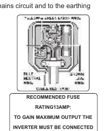
- The Sealey TIG200HFACDC.V2 is a 200A AC/DC Inverter Welder for TIG and MMA applications. It requires a 230V supply, with a 30A supply recommended for maximum output. p. 1, 2
Key actions
- Connect leads for MMA p. 3
- Connect leads for TIG p. 3
Problems and fixes
Over Temperature Indicator lights up
Allow the welder to cool down before continuing.
p. 4Maintenance and reset
- Clean dust from inside p. 4
Technical specifications
| Parameter | Value | Meaning | Pages |
|---|---|---|---|
| Power Output | 10-200A | Welding current range | p. 2 |
| Absorbed Power | 8kW | Power consumption | p. 2 |
Where to find it in the PDF
- Operation p. 3, 4
Table of contents
Manual images
Click an image to enlargeQuick Guide
The Sealey TIG200HFACDC.V2 is a 200A AC/DC Inverter Welder designed for TIG and MMA welding. For maximum output, a 30A supply is required. Always ensure the unit is correctly earthed and that the power supply is stable. Use the front panel controls to select welding modes and adjust parameters like current, pulse, and gas flow.
Safety Instructions
Electrical Safety: Ensure all electrical equipment is checked before use. Use an RCD with portable products. If using a generator, it must be self-regulating and stable. Do not pull the unit by the power cable.
General Safety: Wear appropriate PPE, including a welding head shield and gauntlets. Keep the working area clean, tidy, and well-ventilated. Do not weld near flammable materials. Unplug the unit before performing maintenance.
Operation
Lead Connection: For MMA mode, connect the electrode holder to the Positive (+) connector and the earth lead to the Negative (-) connector. For TIG mode, connect the earth clamp to the Positive (+) connector and the TIG torch to the Negative (-) connector.
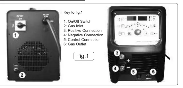
Gas Connection: Connect the regulator to the gas inlet on the back and the gas outlet on the front using the supplied tubing. Secure with worm drive clamps. Test for leaks before use.
Control Connection: Connect the torch trigger or optional foot pedal (TIG200HFACDCF) to the control connection on the front panel.
Welding Modes
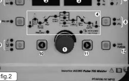
The welder supports multiple modes, including MMA, DC TIG, DC Pulse TIG, AC TIG, and AC Pulse TIG. Use the Up/Down keys to select the welding mode and the adjustment knob to set parameters. 2-touch and 4-touch trigger controls are available for TIG welding.
Maintenance
Periodically remove the covers and clean the inside of the machine with a low-pressure air jet or vacuum cleaner to prevent dust build-up. Avoid resting the torch on hot surfaces. Check the condition of gas tubing and connections regularly.
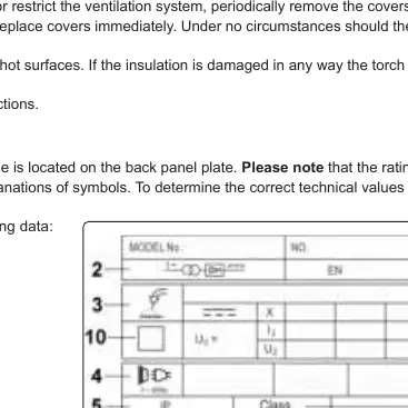
Ratings Plate Symbols
The ratings plate on the rear provides technical data, including the BS/EU standard, inverter-transformer-rectifier symbols, output ratings (U0, I2, U2), and duty cycle information. The duty cycle is based on a 10-minute cycle (e.g., 20% indicates 2 minutes welding and 8 minutes rest).
Manufacturer information
Sealey Group
Practical help
Common problems
Overheating
If the Over Temperature Indicator lights up, allow the welder to cool down before continuing.
Poor electrical contact
Ensure sufficient copper strands are exposed and turned back in the dinse plug when assembling the work clamp cable.
Gas leaks
Test for leaks after opening the regulator and cylinder valve. Ensure tubing is secured with clamps.
Before use
- Check power supply, leads, and plugs for wear or damage.
- Ensure the unit is correctly earthed via a three-pin plug.
- Verify the voltage matches the power supply.
- Ensure adequate ventilation in the working area.
- Wear appropriate PPE (welding head shield, gauntlets).
- Ensure the workpiece is correctly secured.
Specs in practice
- Electrode Capacity
- Ø1.6-4mm range for welding electrodes.
Images and diagrams
- Fig 1: Front panel connections including On/Off switch, Gas Inlet/Outlet, and Positive/Negative/Control connections.
- Fig 2: Control panel layout showing the adjustment knob, displays, and mode selectors.
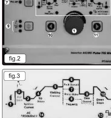
- Fig 3: Procedure parameters diagram detailing indicators for pre-flow, current, pulse settings, and AC frequency.
Model compatibility
- Requires a 30A supply for maximum output.
- Optional foot pedal (TIG200HFACDCF) available for current control.
- Optional electrode holder (MMA01) available.

Manual page author
David Miller
Documentation analyst
Organizes user manual content into clear summaries, with attention to model details, product context, and everyday usability.