Tools / Welding Equipment
User Manual for Sealey INVMIG200 Inverter Welder
Comprehensive user guide for the Sealey INVMIG200 Inverter MIG, TIG, and MMA Welder. Includes setup, welding procedures, maintenance, and safety instructions.
Quick answers from the manual
Quick answer
- The Sealey INVMIG200 is a 4-in-1 inverter welder for MIG, TIG, and MMA welding. It requires a 32A fused supply and supports wire spools up to 5kg. p. 2
Key actions
- Change to gasless welding p. 4
- Adjust wire tension p. 3
First start
- Ensure 32A supply is available. p. 1
- Connect earth clamp and set voltage switch. p. 4
Problems and fixes
Thermal overload
Allow the unit to cool; the thermostat will automatically reset.
p. 5Maintenance and reset
- Thermal overload reset p. 5
Technical specifications
| Parameter | Value | Meaning | Pages |
|---|---|---|---|
| Duty Cycle (MIG) | 20% @ 200A, 60% @ 115A | Welding capacity over a 10-minute cycle. | p. 2 |
| Supply | 230V ac | Required input voltage. | p. 2 |
| Weight | 21kg | Unit weight. | p. 2 |
Where to find it in the PDF
- Safety Instructions p. 1
- MIG Welding Preparation p. 2, 3, 4
- MMA (Arc) Welding p. 5
- TIG Welding p. 6
Table of contents
Manual images
Click an image to enlargeQuick guide from the manual
The Sealey INVMIG200 is a 4-in-1 inverter welder designed for MIG, TIG, and MMA (Arc) welding. This unit requires a 32A fused power supply. Before use, ensure the machine is placed in a well-ventilated area, the earth clamp is securely attached to the workpiece, and you are wearing appropriate safety gear, including a welding head shield and gauntlets.
Preparation for MIG Welding
To prepare the machine for MIG welding, follow these steps:
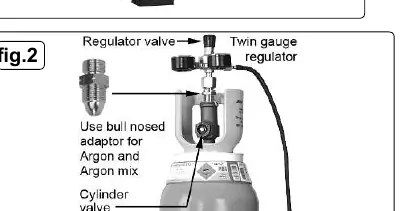
- Gas Setup: If using gas, attach the regulator to the cylinder. 'Crack' the cylinder valve briefly to clear dust before attaching. Use a bull nose adaptor for Argon/Argon mixtures. Connect the gas hose to the regulator and the welder inlet spigot. Set flow rate to 5-8 litres/min.
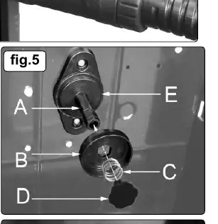
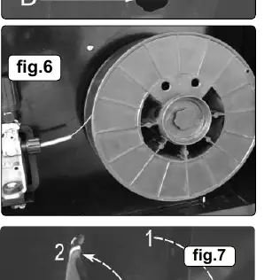
- Wire Spool Installation: Remove the retaining knob, spring, and disc. Slide the wire reel onto the spindle, ensuring the wire feeds off the top towards the drive unit. Replace the disc, spring, and knob, locking it in place.
- Feeding Wire: Open the wire feed mechanism. Ensure the feed roller groove matches the wire diameter (0.6mm or 0.8mm). Straighten 40-50mm of wire and feed it through the liner into the torch. Close the mechanism and set the tension knob to a medium setting (between 2 and 3).
- Torch Connection: Align the Euro connector pins with the socket on the front panel and rotate the locking ring clockwise to secure.
MIG/MAG Welding
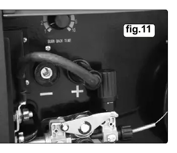
The welder is factory-set for gas welding (torch to positive, earth to negative). To weld without gas (flux-cored wire), you must reverse the polarity: connect the torch cable to the negative (-) terminal and the earth cable to the positive (+) terminal. Ensure the machine is unplugged before changing polarity.
MMA (Arc) Welding
For Arc welding, set the selector switch to the 'Arc' position. Ensure the torch connector plug is disconnected from the front panel sockets. Connect the electrode holder to the positive (+) terminal and the work clamp to the negative (-) terminal. Always refer to the electrode packaging for recommended polarity and current settings.
TIG Welding
Set the selector switch to the 'TIG' position. Note that TIG leads are not included. Connect the TIG torch cable to the negative (-) socket and the work clamp to the positive (+) socket. Sharpen the electrode axially on a grinding wheel for best results.
Maintenance
- Wire Feed Unit: Clean rollers weekly, especially the feed groove, to remove dust.
- Torch: Clean the liner using compressed air. Replace if clogged.
- Contact Tip & Gas Cup: Keep free from spatter. Replace the contact tip if the hole becomes enlarged or oval. Use anti-spatter spray to prolong life.
- Internal Cleaning: Periodically remove the casing and use low-pressure air (max 1 bar) to remove dust from inside. Do not direct air onto electronic circuit boards; use a soft brush instead.
Manufacturer information
Sealey Group
Practical help
Common problems
Wire slipping or binding
Check that the wire diameter matches the drive roller groove size, torch tip size, and liner. Ensure wire is under proper tension.
Machine overheating
The thermal overload protection has triggered. Allow the machine to cool until the yellow LED turns off.
Poor weld quality
Check gas flow, ensure the workpiece is clean (free of oil/rust), verify correct polarity, and check electrode condition.
Before use
- Inspect power cables and plugs for wear or damage.
- Ensure the power supply is 32A fused.
- Verify the gas cylinder is secured in a vertical position.
- Wear welding gauntlets and a welding head shield.
- Ensure the work area is well-ventilated and free of flammable materials.
Specs in practice
- Electrode Capacity
- Supports electrodes from Ø1.6mm to Ø4.0mm.
- Absorbed Power
- 9.3kW maximum power consumption.
Images and diagrams
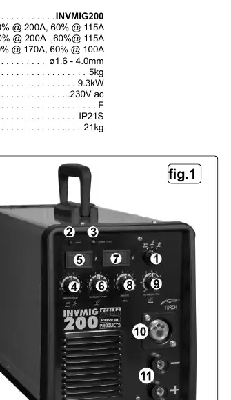
- Fig 1: Front panel controls and indicators.
- Fig 2: Gas regulator and cylinder connection.
- Fig 5-7: Wire spool installation and feed mechanism adjustment.
- Fig 11: Polarity change terminals for gas/gasless welding.
Model compatibility
- Requires a minimum 32A fused supply.
- TIG leads are not included (Sealey INVTIG2 is suitable).
- Arc welding cables are not included (Sealey INVMMA2 is suitable).

Manual page author
Emily Carter
User documentation editor
Prepares concise manual descriptions and highlights the most useful setup, operation, and maintenance information for readers.