Tools / Welding Equipment
User Manual for Sealey MW180i and MW200i MMA Inverter Welders
Comprehensive user guide for Sealey MW180i and MW200i MMA Inverter Welders. Includes setup, welding procedures, safety precautions, maintenance, and troubleshooting.
Quick answers from the manual
Quick answer
- The Sealey MW180i and MW200i are MMA inverter welders suitable for arc and TIG welding. They feature thermal cut-out, anti-stick, arc force, and hot start functions. They require a 230V power supply. p. 2
Key actions
- Connect welding cables p. 3
- Perform arc welding p. 4
First start
- Ensure the machine is switched off and disconnected from the mains before connecting cables. p. 2
Problems and fixes
Overheat indicator illuminated
Allow the inverter to cool down naturally.
p. 3Maintenance and reset
- Clean the machine periodically with low-pressure air (max 1 bar). p. 4
Technical specifications
| Parameter | Value | Meaning | Pages |
|---|---|---|---|
| Welding Current (MW180i) | 20-180A | Adjustable welding current range. | p. 2 |
| Welding Current (MW200i) | 20-200A | Adjustable welding current range. | p. 2 |
| Supply Voltage | 230V | Required mains voltage. | p. 2 |
Where to find it in the PDF
- Safety Instructions p. 1, 2
- Specifications p. 2
- Controls and Operation p. 3
- Maintenance and Troubleshooting p. 4
Table of contents
Manual images
Click an image to enlargeQuick guide from the manual
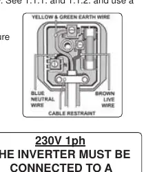
The Sealey MW180i and MW200i are compact MMA inverter welders designed for arc welding and TIG welding (with optional kit). This manual covers safety, setup, operation, and maintenance. Always ensure the machine is disconnected from the mains before connecting cables or performing maintenance. The unit requires a 230V supply and should be connected to a 32A supply for maximum output.
Safety Precautions
- Electrical Safety: Ensure power cables and plugs are in good condition. Use a Residual Current Device (RCD) and ensure the supply is protected by a type C breaker.
- Operator Safety: Wear welding gauntlets and protective head shields. Do not weld near flammable materials or in unventilated spaces.
- Environment: Keep the work area clean, dry, and well-lit. Ensure adequate ventilation to avoid toxic fumes.
Preparation and Cable Connection
Before connecting cables, ensure the machine is unplugged. Refer to the electrode packaging for correct polarity and current settings.
- Electrode Holder: Connect to the positive terminal for standard ARC welding.
- Work Clamp: Connect to the terminal not occupied by the electrode holder. Attach the clamp as close to the weld as possible on the workpiece or a metallic workbench.
- Connections: Ensure cable connectors are turned fully into the quick plugs to prevent overheating.
Operating Instructions
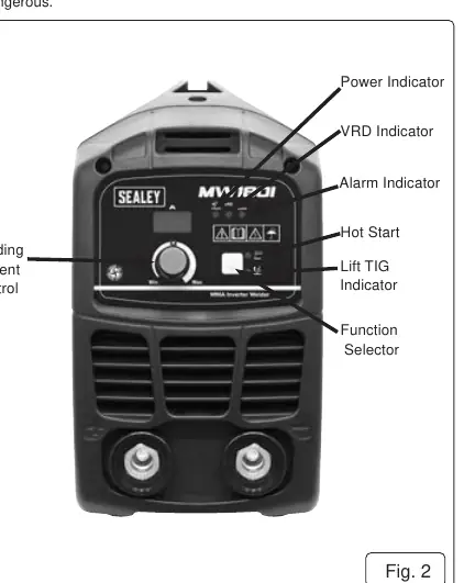
The front panel features controls for welding current, VRD (Voltage Reduction Device), Hot Start, and Lift TIG functions.
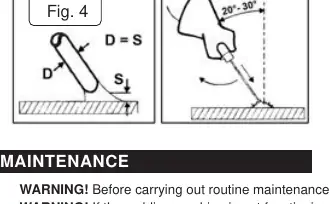
- Welding Procedure: Strike the electrode like a match. Maintain a distance from the workpiece equal to the electrode diameter and keep an angle of 20º to 30º while advancing.
- Hot Start: Increases amperage briefly to help start the arc without sticking.
- Lift TIG: Allows for easy arc starting by touching the tungsten electrode to the job and lifting it off.
Maintenance
- Periodically remove the casing and clean dust from inside the machine using low-pressure air (max 1 bar).
- Do not direct compressed air onto electronic circuit boards; use a soft brush instead.
- Ensure all electrical connections are tight and wiring is free from damage.
- If the case is opened, wait 10-15 seconds after switching off for the capacitor to discharge.
Troubleshooting
- Power lamp not on: Check mains supply.
- Overheat indicator on: Thermal cut-out has activated; allow the machine to cool down naturally.
- Electrode sticking: Adjust current settings or use the Hot Start feature.
- Poor weld quality: Check that the work clamp is securely attached to the workpiece and the surface is clean (free of grease/paint).
Manufacturer information
Sealey Group
Practical help
Common problems
Overheat indicator is illuminated
The thermal cut-out has activated. Allow the machine to cool down naturally before restarting.
Power lamp is not illuminated
Check the mains power supply and connections.
Electrode sticks to the workpiece
Ensure the welding current is suitable for the electrode diameter. Use the Hot Start feature to assist arc initiation.
Poor electrical contact or overheating at connectors
Ensure cable connectors are turned fully into the quick plugs.
Before use
- Inspect power cables, plugs, and connectors for wear or damage.
- Ensure the voltage matches the power supply.
- Wear safety welding gauntlets and eye protection.
- Ensure the work area is well-ventilated and free of flammable materials.
- Check that the work clamp is securely attached to the workpiece.
Images and diagrams
- Fig 1: Back panel showing the rocker switch for power.
- Fig 2: Front panel showing current control, indicators (Power, VRD, Alarm), and function selector.
- Fig 4: Welding technique showing the correct 20-30 degree angle for the electrode.
Model compatibility
- Requires a 32A supply for maximum output.
- Optional TIG accessory kit (Model No. TIG10S) is available.
- Suitable for rutile, basic, and stainless steel rods.

Manual page author
David Miller
Documentation analyst
Organizes user manual content into clear summaries, with attention to model details, product context, and everyday usability.