Electronics / Video Transmission
User Manual for SIIG 04-136A HDMI Over IP Extender
Quick guide for the SIIG 04-136A HDMI Over IP Extender. Learn how to set up point-to-point or matrix configurations, configure IP settings, use the IR pass-back feature, and manage device IDs.
Table of contents
Manual images
Click an image to enlargeImportant Information
Before installing the SIIG 04-136A HDMI Over IP Extender, please note the following requirements and warnings:
- Use CAT5e/6 cables with 100% copper wiring and IEEE-568B standard.
- Dedicated IGMP Gigabit Ethernet switches are highly recommended for optimal performance.
- Do not mix up the transmitter (TX) and receiver (RX) units during installation.
- Ensure the transmitter and receiver channels are different; otherwise, the system may break down.
- If connecting to an existing network, it is recommended to configure a dedicated VLAN to avoid traffic collisions.
Product Overview
The SIIG 04-136A is an HDMI Over IP Extender with IR support. It allows for scalable and flexible input-output matrix configurations, supporting up to 100 inputs to an infinite number of outputs. It supports resolutions up to 1080p 60Hz full HD and transmission distances of up to 120 meters via CAT6 cable.
Package Contents
- Transmitter unit and Receiver unit
- User Manual
- IR blaster and receiver extension cables
- Power adapters (DC5V/2A) x 2
- Remote control
- 3-pin phoenix connectors x 2
- Wall-mount kits x 2
Device Layout
Transmitter Unit: Features an IR window, Power LED, TX ID display, Reset button, Power jack, Data LED, RJ45 output, Link LED, IR output, HDMI output (local), HDMI input, and RS232 port.
Receiver Unit: Features an RX ID display, IR window, Power LED, TX Connected display, Reset button, Power jack, Data LED, RJ45 input, Link LED, IR input, HDMI output, and RS232 port.
Installation and Application
The system supports two main configurations:
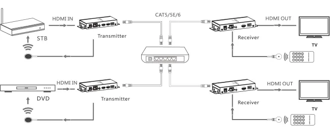
- Point-to-point: Connect the HDMI source to the Transmitter, use a CAT5e/6 cable to connect the Transmitter to the Receiver, and connect the Receiver to the display.
- Matrix configuration: Connect multiple transmitters and receivers to an IGMP Gigabit Ethernet switch. The system supports a maximum of 256 combined units, limited to 100 transmitter units.
Network Configuration
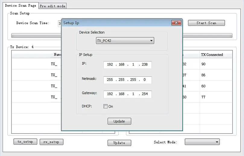
The default IP addresses are 192.168.1.238 for the Transmitter and 192.168.1.239 for the Receiver. If your network has DHCP enabled, the units will be assigned IP addresses automatically. To reset to default IP addresses, disconnect the unit from the network, press the Reset button, and power cycle the device.
Computer Control
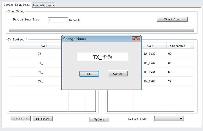
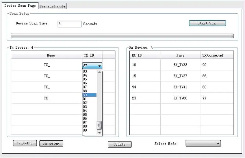
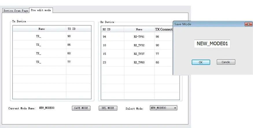
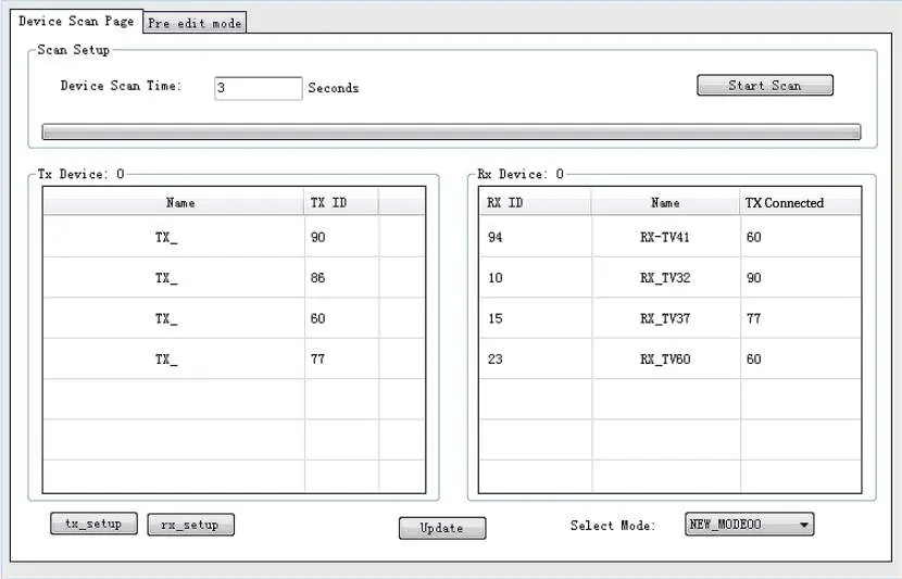
The HDBitT E-Matrix Control Center application (Windows only) allows for advanced management. Download it from www.hdbitt.com/download-matrix. Connect your computer to the network, ensure it is on the same subnet as the TX/RX units, and open the application to scan for devices, set IP addresses, change device names, and manage operating modes.
IR and Device ID Control
Use the included remote control to set or select the TX ID on the transmitter and the TX Connected ID on the receiver for device pairing. You can also use the buttons on the device to change the Device ID and Connection ID to the desired number.
Wireless Control
You can use the "Matrix Control Lite" app for Android or Apple to manage the system. Ensure a wireless router/access point is connected to the dedicated LAN, log in, and scan for TX and RX units.
Official resources from the manual
Manufacturer information
SIIG, Inc.
Practical help
Common problems
System breakdown or failure
Ensure the transmitter and receiver channels are different. Check that you are using IGMP switches.
Device not detected by software
Press the Reset button on the unit and ensure it is on the same network subnet as your computer.
Matrix Control Center application not working properly
Close and restart the application to clear previous settings.
Before use
- Use CAT5e/6 cables with 100% copper wiring.
- Use IGMP Gigabit Ethernet switches for best performance.
- Do not mix up transmitter and receiver units.
- Ensure the transmitter and receiver are on the same network subnet.
- Download the HDBitT E-Matrix Control Center for Windows for advanced configuration.
Specs in practice
- Transmission distance
- Up to 120 meters via CAT6 cable.
- Default IP (TX)
- 192.168.1.238
- Default IP (RX)
- 192.168.1.239
Images and diagrams
- The matrix configuration diagram shows how to connect multiple transmitters and receivers through a network switch.
- The software interface diagrams illustrate how to scan for devices, set IP addresses, and manage operating modes.
Model compatibility
- Matrix Control Center software is compatible with Windows only.
- Supports IEEE-568B wiring standard.

Manual page author
David Miller
Documentation analyst
Organizes user manual content into clear summaries, with attention to model details, product context, and everyday usability.