Electronics / Video Transmission
Full HD HDMI Extender over IP with POE, RS-232 & IR
Quick setup and configuration guide for the SIIG Full HD HDMI Extender over IP. Learn how to connect devices, configure multicast/screen wall settings, and use the PC control tool.
Table of contents
Manual images
Click an image to enlargeQuick Guide from the Manual
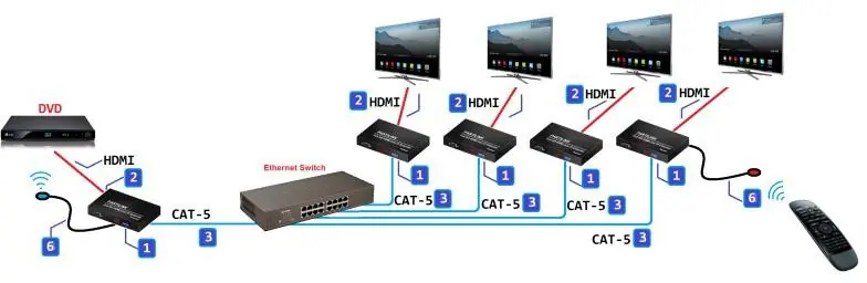
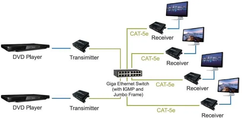
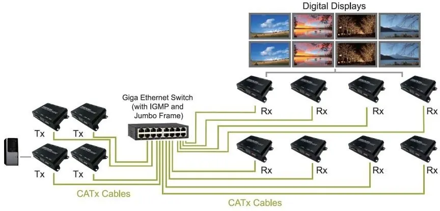
This document provides instructions for the SIIG Full HD HDMI Extender over IP (Model 04-1284B). The system supports point-to-point, unicast, multicast, and screen wall configurations. Key features include RS-232 bi-directional extension, IR control extension, and PoE support. Configuration is managed via a dedicated PC tool.
Hardware Description
The system consists of a Transmitter (TX) and a Receiver (RX).
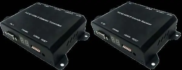
Transmitter (TX)
- Power Input: 2.0mm jack for DC5V/2A.
- LAN Port: RJ-45 for 10/100 BASE-T CAT5 extension.
- HDMI Input: Type-A female connector.
- HDMI Output: Type-A female connector for loop-through.
- IR Port: 3.5mm jack for IR emitter.
- RS-232: DB-9 female connector.
- Configuration: 6-bit DIP switch for channel selection (0-63).
Receiver (RX)
- HDMI Output: Type-A female connector.
- IR Port: 3.5mm jack for IR receiver.
- Other ports: Same power, LAN, and RS-232 configuration as the transmitter.
Installation
- Set the group ID on both the transmitter and receiver using the DIP switch.
- Connect HDMI cables between the source and transmitter, and the display and receiver.
- Connect the CAT5 cable between the transmitter, Ethernet switch, and receiver.
- Connect the DC5V power adapter to both units.
- Turn on the source device.
- Connect IR emitter/receiver cables if remote control is required.
Configuration via PC Tool
The system is managed using the IPTV_Control_Center.exe tool. Disable system Firewall or Antivirus software before running the tool.
Network Setup
- DHCP: The extender has DHCP enabled by default.
- Static IP: If no DHCP server is present, the default IP is 169.254.xxx.xxx. Set your PC to a static IP in the same range (e.g., 169.254.11.11) with a subnet mask of 255.255.0.0.
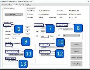
Using the Tool
- Connect the PC to the same Ethernet switch.
- Run the tool and click Start Scan in the Device Scan Page.
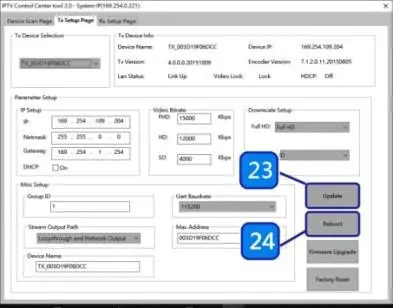
- Use the TX Setup Page and RX Setup Page to configure specific parameters like IP address, Video Bitrate, Group ID, and Stream Output Path.
- Click Update to save settings.
Web User Interface
The system can also be configured via a web browser.
- Default Login: User Name: admin, Password: 123456.
- Functions: Allows firmware upgrades, multicast enabling, and device rebooting.
Troubleshooting and Maintenance
- Factory Reset: If the system is unstable or settings are incomplete, click the Factory Reset button in the PC tool to restore defaults.
- Firmware Upgrade: Use the Firmware Upgrade button in the PC tool or web interface to update the system.
- Reboot: Use the Reboot button to restart the device after configuration changes.
Official resources from the manual
Manufacturer information
SIIG, Inc.
Practical help
Common problems
System unstable or settings incomplete
Click 'Factory Reset' in the PC tool to recover initial default settings.
Cannot find extender in software
Ensure the PC is on the same network or set a static IP to 169.254.xxx.xxx.
Software connection issues
Disable system Firewall or Antivirus software when using the configuration tool.
Before use
- Ensure you have a 10/100 BASE-T switch hub.
- Use CAT-5 or CAT-5e cables for network connection.
- Verify HDMI cables are connected to the source and display.
- Set TX and RX to the same group ID using the DIP switch.
- Disable Firewall/Antivirus on the PC used for configuration.
Specs in practice
- Video Bitrate
- Adjusts the resolution bitrate for each group.
- ESD Protection
- Air gap discharge ±8KV, contact discharge ±4KV.
Images and diagrams
- DIP Switch settings map channel numbers 00-63 to specific switch configurations.
- PC Tool interface allows scanning, IP setup, and firmware upgrades.
Model compatibility
- Requires 10/100 BASE-T switch hub.
- Supports point-to-point, unicast, multicast, and screen wall configurations.

Manual page author
Michael Turner
Technical manual editor
Reviews PDF manuals for structure, safety notes, and practical product details so readers can find the right information quickly.