Automotive / Parts & Accessories
Assembly Instructions for Simon Rack Simonlocker 180x30x50 cm
Quick assembly guide for the Simon Rack Simonlocker 180x30x50 cm. Includes a detailed parts list, step-by-step installation instructions, and information on compatible accessories.
Table of contents
Manual images
Click an image to enlargeQuick guide from the manual
This document provides assembly instructions for the Simon Rack Simonlocker (180 x 30 x 50 cm). The product is delivered in an unassembled state. Please ensure you have all parts listed below before beginning the assembly process. The assembly requires the use of the provided Allen key and follows a specific sequence of steps to ensure structural integrity.
Parts list
Before starting, verify that you have all the following components:
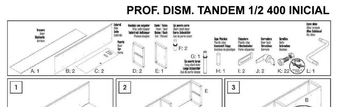
- A: Side panel
- B: Side panel
- C: Back panel
- D: Tray with hanger
- E: Floor/Roof panel
- F: Short shelf door
- G: Long shelf door
- H: Plastic stop
- I: Plastic stop
- J: Door lock
- K: Screws
- L: Allen key
Assembly instructions
Follow these steps to assemble your locker:
- Prepare the side panels (A, B) and back panel (C).
- Connect the floor/roof panels (E) to the side and back panels. Ensure the floor is placed with the hollow side facing down.
- Install the tray with hanger (D) inside the unit.
- Attach the doors (F, G) to the frame.
- Install the plastic stops (H, I) to ensure proper door closure.
- Secure the door locks (J) into the designated slots.
- Use the provided screws (K) and Allen key (L) to tighten all connections.
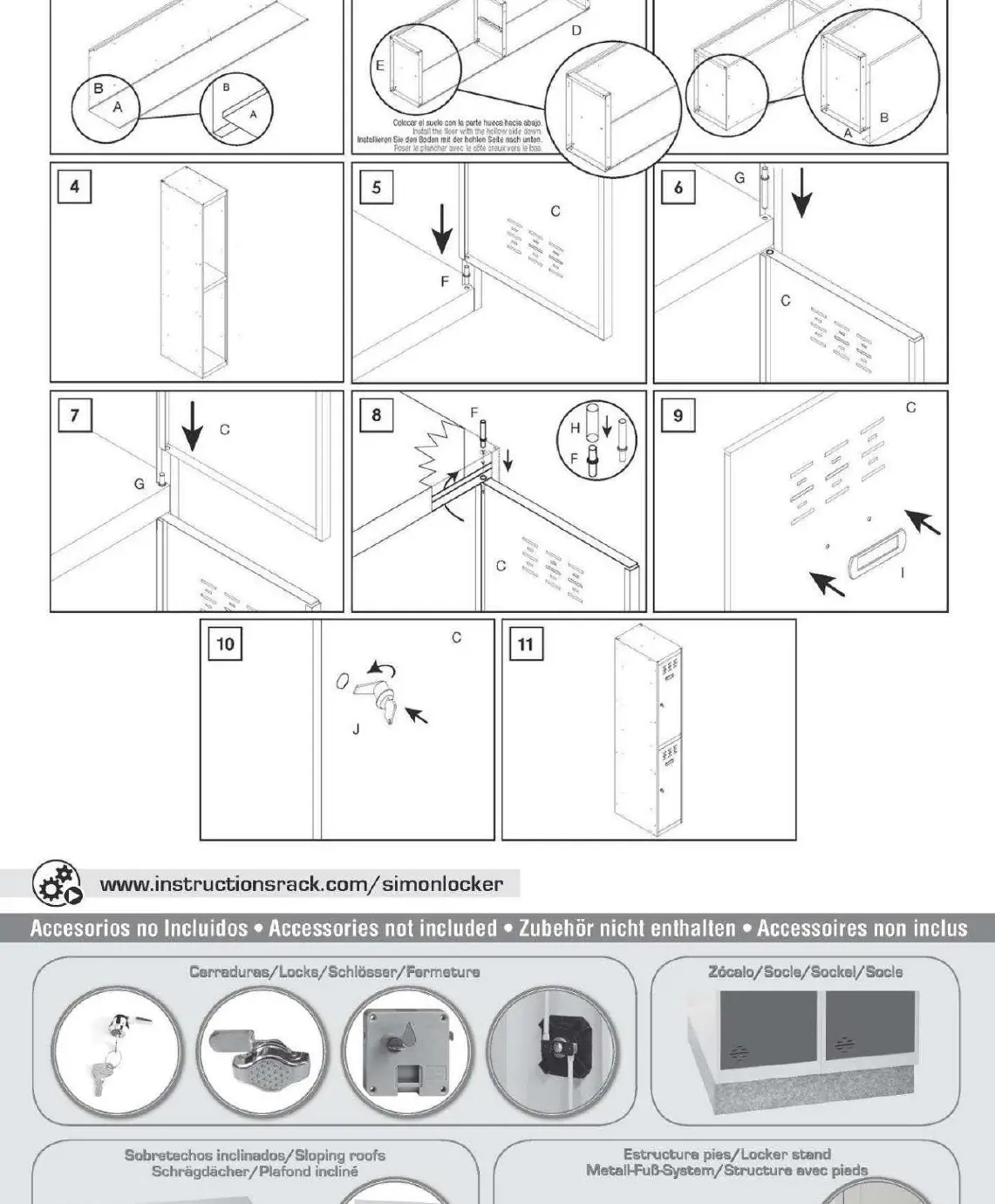
Accessories
Please note that the following items are not included with the base unit and must be purchased separately:
- Locks
- Base/Plinth
- Sloping roofs
- Locker stands (feet)
Practical help
Common problems
Product arrives unassembled
This is the standard delivery format. Follow the 11-step assembly guide provided in the manual to build the unit.
Missing accessories
Items such as locks, bases, sloping roofs, and feet are not included in the standard kit and are sold separately.
Before use
- Verify all parts (A-L) are present before starting assembly.
- Ensure you have the provided Allen key (L) ready.
- Clear a workspace for assembly.
- Follow the step-by-step sequence 1-11 carefully.
- Ensure the floor panel is installed with the hollow side facing down.
Specs in practice
- Assembly Type
- Unassembled (Dismantled) kit requiring manual installation.
Images and diagrams
- The manual uses a letter-coded system (A-L) to identify panels, screws, and tools.
- Steps 1-11 illustrate the physical connection of panels and locking mechanisms.
Model compatibility
- Compatible with optional accessories: Locks, Base/Plinth, Sloping roofs, and Locker stands (feet).

Manual page author
David Miller
Documentation analyst
Organizes user manual content into clear summaries, with attention to model details, product context, and everyday usability.