Tools / Pressure Washers
User Manual for Simpson 50127 1500V True RMS Digital Clamp Meter
Quick guide for the Simpson 50127 1500V True RMS Digital Clamp Meter. Learn how to use the unique rotary jaw mechanism, perform voltage, current, resistance, and temperature measurements, and maintain your device safely.
Table of contents
Manual images
Click an image to enlargeQuick guide from the manual
The Simpson 50127 is a True RMS digital clamp meter designed for high-voltage applications up to 1500V DC and 1000V AC. It features a unique rotary jaw mechanism for accessing conductors in congested areas and a safe trigger mechanism to keep hands at a safe distance from live parts. Before use, ensure the battery is installed and test leads are in good condition. Always keep hands behind the safety limit marked on the device.
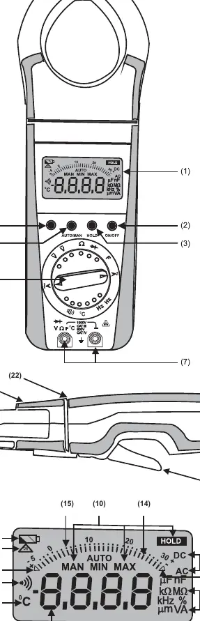
Device overview
The device features a liquid crystal display, a function selector switch, and several pushbuttons for manual range selection, data hold, and MIN/MAX storage. The rotary jaw mechanism allows the jaws to be rotated up to 90 degrees in either direction, enabling the display to face the user while measuring vertical bus bars or overhead cables.
Safety precautions
- Operators must use individual protective equipment if hazardous live parts are accessible.
- Keep hands and fingers behind the edge that separates the rotating jaws from the hand-held part.
- Do not work alone in shock-hazardous environments.
- Maximum permissible voltage between terminal sockets and ground is 1000V AC and 1500V DC.
- Do not use the meter if obvious wear in the jaw opening is visible.
Operation
Switching ON: Press the ON/OFF pushbutton. A sound signal acknowledges the power-up, and all LCD segments will appear briefly.
Automatic Turn-OFF: The meter turns off automatically after approximately 10 minutes of inactivity. To prevent this, press the yellow multi-function pushbutton and the ON/OFF button together to select the CONTINUOUSLY ON mode.
Range Selection: The meter features autoranging for most functions. Manual range selection can be activated by pressing the AUTO/MAN button.
Measurement procedures
Voltage Measurement: Set the function selector to V~ or V. Connect test leads to the terminal sockets.
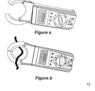
Current Measurement: Set the function selector to A. Open the jaws using the safe trigger mechanism and clamp around the cable. Ensure the conductor is at the center of the jaw for best accuracy.
Resistance, Diode, and Continuity: Set the function selector to the appropriate symbol. For small resistance values, use the zero adjustment feature by shorting the leads and pressing the yellow multi-function button.
Temperature Measurement: Compatible with Pt100 and Pt1000 sensors. Connect the sensor and press the yellow multi-function button to switch to temperature mode.
Special features
- Data HOLD: Press the HOLD button to freeze the measured value on the display.
- MIN/MAX: Use this function to monitor and store minimum and maximum measured values over time.
- Backlight: Press AUTO/MAN and HOLD simultaneously to toggle the display backlight.
Maintenance
Battery Replacement: When the low battery symbol flashes, replace the 9V battery. Disconnect the meter from the measuring circuit before opening the battery cover located at the rear bottom side. Use a 9V flat cell battery (IEC 6F22 or IEC 6LR61).
Cleaning: The surface between the opening jaws should be cleaned with a dry cloth. Avoid cleansers, abrasives, or solvents.
Practical help
Common problems
Incorrect display or blocked measuring process
Reset the meter by switching it OFF and ON again. Check battery connections.
OL displayed on screen
The measured value exceeds the selected range.
Battery symbol flashes
Replace the 9V battery immediately to maintain measurement accuracy.
Before use
- Check test leads for cracked insulation or open circuits.
- Ensure the battery is installed and not leaking.
- Verify the device is not damaged.
- Ensure hands are behind the safety limit (22) during measurement.
- Verify the device is set to the correct function and range.
Specs in practice
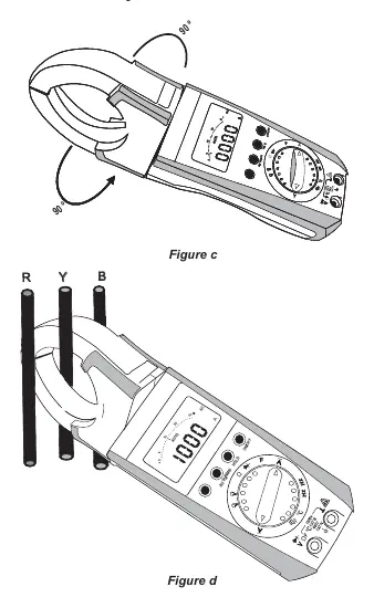
- Rotary mechanism
- Allows the clamp jaws to rotate 90 degrees for better access in tight spaces.
Images and diagrams
- Figure a/b: Demonstrates current measurement using the safe trigger mechanism.
- Figure c/d: Shows the rotary jaw mechanism for accessing vertical bus bars.
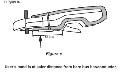
- Figure e: Illustrates the safe trigger mechanism to keep hands at a safe distance.
Model compatibility
- Compatible with Pt100 and Pt1000 temperature sensors.
- Max voltage: 1000V AC / 1500V DC.
- Max current: 1500A.

Manual page author
Michael Turner
Technical manual editor
Reviews PDF manuals for structure, safety notes, and practical product details so readers can find the right information quickly.