Tools / Measuring Tools
Indicator Light Replacement Guide for Solinst 101/102/102M Water Level Meter
Step-by-step repair instructions for replacing the indicator light on Solinst 101, 102, and 102M Mk2 Water Level Meters. Includes soldering procedures, wiring diagrams, and assembly tips.
Table of contents
Manual images
Click an image to enlargeQuick Guide for Indicator Light Replacement
This guide provides instructions for replacing the indicator light on Solinst Mk2 Water Level Meters (Models 101, 102, and 102M). Note that for Mk1 meters, you will require the Mk2 Circuit Board Assembly (#102977). Always ensure the battery is removed before beginning any work on the circuit board.
Tools and Materials Required
- WLM Replacement LED (Light) Assembly (Spare) (#113923)
- Phillips Screwdriver
- 10 mm (3/8") Wrench
- Wire Cutters and Wire Strippers (if required)
- Solder Wire with Flux
- Soldering Iron
Preparation and Removal
- Remove the battery from the reel hub.
- Unscrew the three screws and remove the faceplate.
- Press down on the white terminals of the push-release fittings on the circuit board to remove the tape/cable leads.
- If you have an older style light (leads connected to Sonalert terminals), cut the red and black wires connected to the light and push the light out through the front of the faceplate.
- Use the wrench to unscrew the nut holding the test button and push the button out of the faceplate.
- Unscrew the two screws holding the circuit board from the Sonalert and lift the board to access the connections.
Installing the New Light
- If you have a newer style light, unsolder it from the circuit board and remove old solder.
- If you had an older style light, insert the new red lens through the front opening in the faceplate and secure it using the white nut.
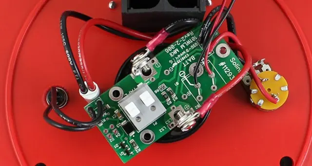
- For Model 101 or 102: Insert the leads of the new light into the two positions labelled "D2" on the circuit board and solder in place.
- For Model 102M: Insert the leads of the new light into the two positions labelled "D4" on the circuit board and solder in place.
Reassembly and Testing
- Place the circuit board assembly back onto the Sonalert, ensuring the sides marked +ve and -ve are aligned with the corresponding terminals.
- Reinstall the two screws to connect the bare wires from the circuit board to the Sonalert terminals.
- Insert the test button through the faceplate opening and secure with the nut.
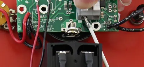
- Connect the tape or cable to the circuit board assembly by pressing the white terminals and inserting the leads. Ensure the negative lead is inserted into the terminal with the white square below it.
- Install the battery.
- Test the unit by placing the probe in a glass of tap water and turning the meter to the 'ON' position. If the light does not activate, check all connections and battery polarity.
- Reattach the faceplate to the reel using the three screws.
Wiring and Tape Orientation
When connecting the tape, note that there is a "P" etched on the tape to help denote the proper orientation (top and bottom leads). The lead on the top of the tape (numbers facing up) is inserted into the terminal with a white square below it on the circuit board.
Practical help
Common problems
Light does not activate after replacement
Check all connections on the circuit board and verify the polarity of the battery.
Difficulty accessing circuit board
Ensure the circuit board is carefully lifted from the Sonalert after removing the two mounting screws.
Before use
- Verify you have the correct replacement LED assembly (#113923).
- Ensure you have a soldering iron and solder wire with flux.
- Remove the battery from the reel hub before starting.
- Identify if your unit uses D2 (101/102) or D4 (102M) soldering positions.
Images and diagrams
- The circuit board shows specific terminals for the tape/cable leads, marked with a white square for the negative lead.
- The tape has a 'P' mark to ensure the top and bottom leads are oriented correctly.
Model compatibility
- Mk1 Water Level Meters require the Mk2 Circuit Board Assembly (#102977) for this repair.
- Model 101 and 102 use D2 positions; Model 102M uses D4 positions.

Manual page author
David Miller
Documentation analyst
Organizes user manual content into clear summaries, with attention to model details, product context, and everyday usability.