Power / Solar Inverters
Installation and Operation Manual for Solis 4G Single Phase Inverter
Comprehensive installation and operation guide for Solis 4G Single Phase Inverters. Includes mounting instructions, electrical connection diagrams, menu settings, troubleshooting, and technical specifications.
Quick answers from the manual
Quick answer
- The Solis 4G Single Phase Inverter is a grid-tied solar inverter. Installation requires mounting on a vertical surface, connecting PV strings (DC), grid connection (AC), and optional monitoring. Operation is managed via the front panel keypad and LCD. p. 1, 9, 23
Key actions
- Start the inverter p. 23
- Stop the inverter p. 23
First start
- Switch on AC, then DC. The inverter will initialize and start generating power after 30-300 seconds. p. 23
Where to find it in the PDF
- Safety Instructions p. 5, 6
- Installation p. 9, 10, 11, 12
- Operation p. 24, 25, 26
Table of contents
Manual images
Click an image to enlargeQuick guide from the manual
This manual provides instructions for the installation, operation, and maintenance of the Solis 4G Single Phase Inverter. Key steps include mounting the unit vertically, connecting the PV array (DC) and grid (AC) cables, and configuring settings via the front panel. Always ensure the inverter is installed in a location that avoids direct sunlight and rain, and that the mounting surface can support the weight of the unit.
Overview
The inverter features a front panel with an LCD display, three LED status indicators (Power, Operation, Alarm), and four keys (ESC, UP, DOWN, ENTER) for menu navigation and settings modification. The bottom of the unit contains the DC input, RS485 communication port, and AC output.
Installation
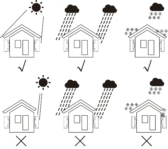
Location: Install the inverter on a wall or strong structure capable of bearing the weight. Ensure adequate ventilation and avoid small, closed spaces. Do not install in areas with high ambient temperatures or direct sunlight/rain.
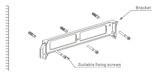
Mounting: The inverter must be mounted vertically. Use the provided wall bracket and secure it with appropriate screws. Maintain a clearance of at least 300mm on all sides and 500mm from the ground.
Electrical Connections:
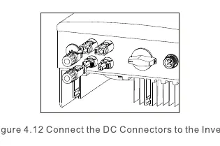
- PV Side: Ensure the PV array open circuit voltage is within the inverter's limit (550V or 600V depending on the model). Use approved DC cables and connectors.
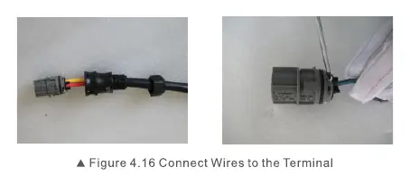
- Grid Side: Use 2.5-6mm² cable. Connect the Line (L) to the L terminal, Neutral (N) to the N terminal, and Earth to the ground terminal.
- External Ground: Connect an external ground conductor to the right side of the inverter using an M4 terminal.
Operation
Start-up: Switch on the Grid Supply Main Switch (AC) first, then the DC Isolator. The inverter will initialize and start generating power after 30-300 seconds.
Menu Navigation: Use the UP/DOWN keys to scroll through options and the ENTER key to access the Main Menu. The menu includes Information, Settings, Advanced Info, and Advanced Settings.
Maintenance and Troubleshooting
The inverter does not require regular maintenance. If the unit is dirty, clean it with a soft brush or damp cloth; do not use solvents. If an alarm message appears on the LCD, refer to the troubleshooting table in the manual. Common issues include 'No power' (check PV connections) or 'Over grid voltage' (check AC cable resistance).
Practical help
Common problems
No power on LCD
Check PV input connections, DC input voltage, and ensure PV+/- is not reversed.
Over grid voltage
Check AC cable resistance; consider using a larger cable size or adjusting the protection limit if allowed by the utility.
Reverse-GRID
Check the polarity of the AC connector.
Over Temperature
Check surrounding ventilation and ensure the inverter is not in direct sunlight during hot weather.
Before use
- Ensure the mounting surface can bear the weight of the inverter.
- Verify the PV array open circuit voltage is within the inverter limit (550V or 600V).
- Check that the AC grid cable is between 2.5-6mm².
- Ensure the inverter is installed vertically with proper clearance.
- Verify all electrical connections are secure and polarity is correct.
Specs in practice
- MPPT voltage range
- The voltage range within which the inverter can track the maximum power point for optimal efficiency.
- Ingress protection (IP65)
- Indicates the unit is dust-tight and protected against water jets.
- Topology (Transformerless)
- A design that eliminates the heavy transformer, resulting in a lighter, more efficient inverter.
Images and diagrams
- Figure 1.2: Bottom side view showing DC input, RS485, and AC output ports.
- Figure 4.1: Recommended installation positions to avoid direct sunlight and rain.
- Figure 4.21: Guidance for a simple installation of an inverter solar energy system.
Model compatibility
- Compatible with Wi-Fi or GPRS monitoring devices.
- Logic interface required for installations in the UK and Belgium.

Manual page author
David Miller
Documentation analyst
Organizes user manual content into clear summaries, with attention to model details, product context, and everyday usability.