Power / Solar Inverters
User Manual for Solis 4G Series Grid Inverter
Comprehensive user guide for the Solis 4G Series single-phase grid-tied inverters (Solis-1P6K-4G-US, Solis-1P7.6K-4G-US, Solis-1P10K-4G-US). Includes installation, operation, troubleshooting, and technical specifications.
Quick answers from the manual
Quick answer
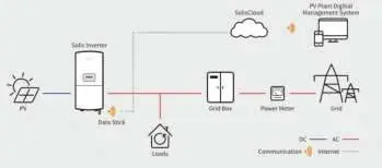
- The Solis 4G Series grid-tied inverter converts DC power from PV modules into AC power for home loads and the grid. Installation requires vertical mounting with specific clearances and electrical connections by qualified personnel. p. 1, 10, 15
Key actions
- Start-up procedure p. 22
- Shutdown procedure p. 23
First start
- Ensure AC switch is ON, then turn on DC switches. The inverter will initialize and start generating power after a delay. p. 22
Problems and fixes
ARC-FAULT
Check DC cables and connections for arcing, then press ESC for 3 seconds to restart.
p. 51, 56Maintenance and reset
- Clean dust from the heat sink using a soft brush. Do not use solvents. p. 52
Technical specifications
| Parameter | Value | Meaning | Pages |
|---|---|---|---|
| Max. input voltage | 600V | Maximum DC input voltage | p. 57, 59, 61 |
| Rated output power | 6kW / 7.6kW / 10kW | Rated power output depending on model | p. 57, 59, 61 |
Where to find it in the PDF
- Installation p. 10, 15
- Troubleshooting p. 53, 56
Table of contents
Manual images
Click an image to enlargeQuick Guide
This manual provides essential instructions for the installation, operation, and maintenance of the Solis 4G Series single-phase grid-tied inverters. Key requirements include vertical mounting, maintaining specific clearances for airflow, and ensuring all electrical work is performed by qualified personnel. The inverter features an integrated DC switch and supports remote monitoring via optional data loggers.
Overview
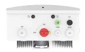
The inverter front panel includes an LCD display, four navigation keys (ESC, UP, DOWN, ENTER), and three status LED indicators (POWER, OPERATION, ALARM). The system diagram illustrates the connection between the PV modules, the inverter, the grid, and the monitoring system.
Installation
Location Selection: Install the inverter in a clean, dry place, protected from direct sunlight, rain, and snow. Ensure the ambient temperature is between -13°F and 140°F (-25°C to 60°C). The unit must be mounted vertically with a maximum incline of +/- 5°.
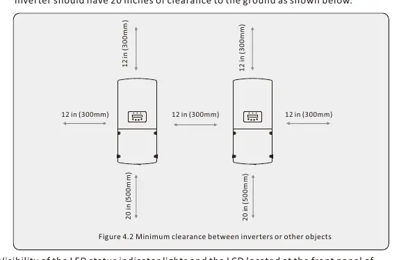
Mounting: Use the provided mounting bracket. Maintain a minimum clearance of 12 inches between adjacent inverters and 20 inches of clearance from the ground.
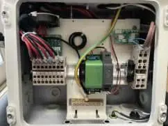
Electrical Connections: Remove the wiring box cover to access terminals. Ensure the grid supply and DC switches are OFF before making connections. Use appropriate conduit knockouts for DC and AC cables. Connect PV strings to DC terminals and grid cables to AC terminals, ensuring correct polarity. Grounding is required at both internal and external connection points.
Operation
Start-up: Turn the AC switch ON, then turn on the DC switches. The inverter will initialize and begin generating power after a safety delay.
Shutdown: Select 'Grid Off' in the advanced settings, turn off the AC switch, wait for capacitors to discharge, then turn off the DC switch.
Menu Navigation: Use the keypad to navigate menus. Advanced settings are password-protected and intended for qualified technicians only. Various working modes (e.g., Volt-Watt, Volt-Var) can be configured to meet grid requirements.
Maintenance
The inverter requires no regular maintenance. Periodically clean dust from the heat sink using a soft brush to ensure proper heat dissipation. Do not use solvents or abrasive materials for cleaning.
Troubleshooting
In case of failure, the LCD will display an alarm message. Common alarms include grid voltage/frequency issues or DC insulation faults. Refer to the troubleshooting table in the manual for specific causes and solutions. If an ARC-FAULT occurs, check DC cables for arcing and press ESC for 3 seconds to restart.
Specifications
The Solis 4G Series inverters support 208V/240V single-phase grids. They feature high efficiency, natural convection cooling, and TYPE 4X ingress protection. Detailed electrical and environmental specifications are provided for each model variant.
Practical help
Common problems
No display (Blank Screen)
Check DC switch, PV connections, polarity, and voltage levels.
Inverter stuck in Initializing
Check PV connections and voltage; ensure no cable damage.
OV-G-V (Over Grid Voltage)
Check AC voltage at inverter; verify Grid Standard settings.
ARC-FAULT
Check DC cables/connections for arcing; press ESC for 3 seconds to restart.
Before use
- Ensure mounting surface is vertical and strong.
- Verify ambient temperature is within -13°F to 140°F.
- Check for sufficient clearance (12" between inverters, 20" from ground).
- Ensure all electrical connections are made by qualified personnel.
- Verify PV string voltage is within inverter limits.
Specs in practice
- Max. input voltage
- Maximum DC voltage the inverter can handle (600V).
- MPPT voltage range
- Operating range for optimal power tracking (100-500V).
- Rated grid voltage
- Compatible grid voltage (240V/208V).
- Ingress protection
- Enclosure rating (TYPE 4X).
Images and diagrams
- Front panel display shows status LEDs and LCD.
- Wiring box interior contains DC/AC terminals and grounding.
- System diagram shows inverter connection to PV, Grid, and Monitoring.
Model compatibility
- Compatible with 208V or 240V single-phase grids.
- Requires qualified personnel for installation.
- Supports remote monitoring via optional Solis data loggers.

Manual page author
Michael Turner
Technical manual editor
Reviews PDF manuals for structure, safety notes, and practical product details so readers can find the right information quickly.