Power / Solar Inverters
Installation and User Manual for Sol-Ark Limitless 18K-2P-LV Hybrid Inverter
Comprehensive installation and user guide for the Sol-Ark Limitless 18K-2P-LV hybrid inverter. Includes mounting instructions, battery and PV integration, wiring diagrams, parallel system configuration, and troubleshooting.
Quick answers from the manual
Quick answer
- The Sol-Ark Limitless 18K-2P-LV is a residential hybrid inverter. It supports 48V battery banks, 3 independent MPPTs for PV, and various grid/generator configurations. Installation requires qualified personnel and adherence to local electrical codes. p. 1, 6, 13
Key actions
- Mounting the inverter p. 9
- Connecting batteries p. 11
- Powering up p. 28
First start
- Check battery voltage (40-60V), PV input voltage (max 500V), and Grid input voltage. Turn on battery breakers, press power button, program settings, then turn on PV and Grid disconnects. p. 28, 29
Problems and fixes
Grid Phase Wrong
Check phase sequence (AB-BC-CA).
p. 55, 56
LCD not powering on
Check power sources (PV/Grid/Battery) and press power button.
p. 76Error codes
| Code | Meaning | Action | Pages |
|---|---|---|---|
| F1 | DC_Inversed_Failure (Parallel system issue) | Not a fault if turning one system off. | p. 78 |
| F63 | Arc_Fault | Check PV connector/connection. | p. 78 |
Maintenance and reset
- Perform a power cycle by turning off all breakers/disconnects, pressing the power button to OFF, waiting ~1 min, then reversing steps. p. 30
Technical specifications
| Parameter | Value | Meaning | Pages |
|---|---|---|---|
| Max. Supported PV Power | 32,400W | Maximum PV array power. | p. 13 |
| Continuous Power | 14,000W | Continuous AC output power. | p. 13 |
Where to find it in the PDF
- Installation p. 8
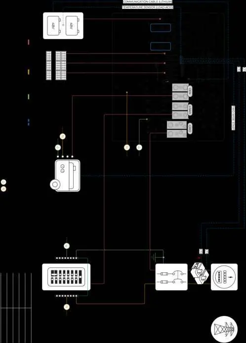
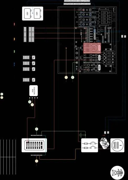
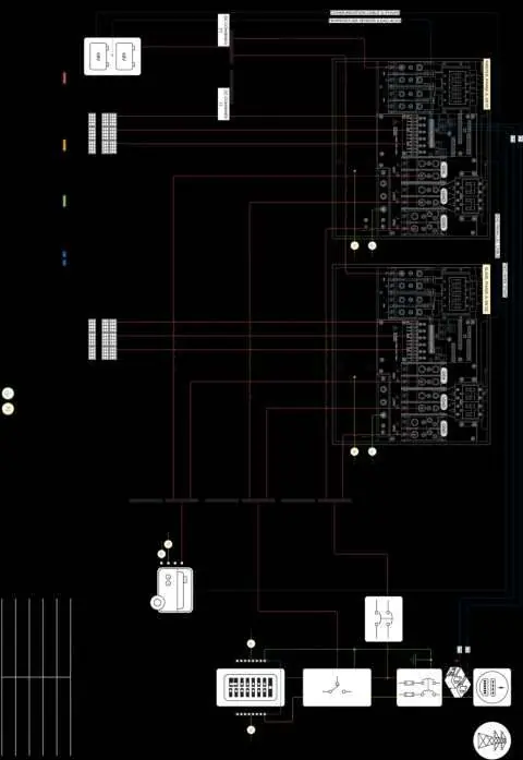
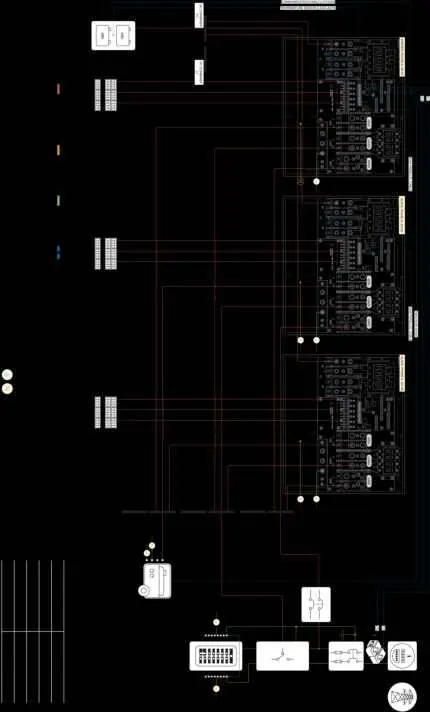
- Wiring Diagrams p. 64
Table of contents
Manual images
Click an image to enlargeImportant Safety Information
Before operating the Sol-Ark 18K-2P-LV, ensure all safety instructions are followed. Only qualified electrical personnel should install, troubleshoot, or service the equipment. Always check utility voltage before turning on the unit and verify the inverter's programmed grid type. The unit is programmed in 120/240V Split-Phase at 60Hz by default.
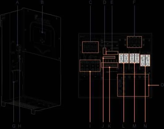
Components and Inputs
The system includes the inverter, French cleat, filter rings, communication cables, temperature sensor, Wi-Fi/Ethernet dongle, and 300A CT sensors. Key inputs include PV DC disconnect, battery breakers, MPPT inputs, GEN terminal, LOAD terminal, and GRID terminal.
Installation
Mounting: Find a location with at least 6 inches of vertical clearance and 2 inches of side clearance for heat dissipation. The unit is NEMA 3R/IP65 rated for indoor or outdoor use. Protect the LCD screen from direct UV exposure.
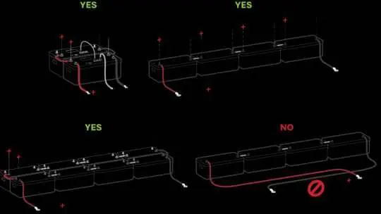
Battery Integration: The system is a 48VDC nominal system. Do not mix battery banks of different make, model, age, or chemistry. Ensure battery breakers are OFF during wiring. Connect batteries to both input terminals if the battery is capable of charging/discharging above 160A.
PV Connection: The inverter has 3 independent MPPTs supporting up to 2 PV strings each. Max VOC is 500V. Ensure correct polarity; backward polarity will cause damage.
Generator Integration: Supports 120/240V Split-Phase generators on the GEN port. For generators >19.2kW, connect to the GRID terminal and configure settings accordingly.
User Interface
The main screen displays power generation, grid usage, load power, and battery status. LED indicators provide system status: DC (Solar), AC (Grid), Normal (Inverting), and Alarm (Fault state).
Parallel Systems
For parallel operation, all units must share the same software version. Program one unit as 'Master' (Modbus SN: 1) and others as 'Slave' (Modbus SN: 2, 3, etc.). Set DIP switches according to the configuration table. A joint battery bank is required for parallel systems.
Troubleshooting
If the system displays 'Grid Phase Wrong', check the phase sequence (AB-BC-CA). For 'LCD not powering on', ensure at least one power source (PV, Grid, or Battery) is connected. Refer to the error code table for specific fault descriptions like F1 (DC_Inversed_Failure) or F63 (Arc_Fault).
Practical help
Common problems
LCD not powering on
Ensure at least one power source (PV, Grid, or Battery) is connected and press the power button.
Grid Phase Wrong error
Check phase sequence (AB-BC-CA) and wiring connections. Use a rotational tester.
Battery cable sparks when connected
Ensure battery breakers are OFF before connecting or disconnecting batteries.
DC LED not on
Verify PV voltage is above 125V and below 500V, check polarity, and ensure PV DC disconnect is ON.
Before use
- Check utility voltage before turning ON the unit.
- Verify inverter grid type (default 120/240V Split-Phase).
- Ensure battery voltage is between 40VDC and 60VDC.
- Check PV input voltage (max 500V).
- Verify all wiring is correct and not pinched.
Specs in practice
- Max. Supported PV Power
- 32,400W total capacity.
- Max. Grid Passthrough Current
- 200A.
- Nominal DC Voltage
- 48V system.
- Enclosure Rating
- IP65 / NEMA 3R (suitable for outdoor use).
Images and diagrams
- Diagram 01: Standard Wiring
- Diagram 04: AC Coupling in LOAD
- Diagram 08: 2 Parallel Inverters 120/240V
- Diagram 10: 2 Parallel Inverters 120/208V Unbalanced 3-Phase
Model compatibility
- Compatible with most standard dimmer switches (performance may vary).
- Requires 48V batteries.
- Supports 120/240V Split-Phase generators.

Manual page author
Michael Turner
Technical manual editor
Reviews PDF manuals for structure, safety notes, and practical product details so readers can find the right information quickly.