Power / Solar Inverters
Installation Guide and User Manual for Sol-Ark 18K-2P-LV Hybrid Inverter
Comprehensive installation and user guide for the Sol-Ark 18K-2P-LV Hybrid Inverter. Includes mounting instructions, wiring diagrams, battery integration, system setup, and troubleshooting.
Quick answers from the manual
Quick answer
- The Sol-Ark 18K-2P-LV is a residential hybrid inverter. This manual covers installation, wiring, battery integration, system programming, and troubleshooting. p. 1
Key actions
- Mounting the inverter p. 9
- Connecting batteries p. 11
- Powering up p. 29
Problems and fixes
DC LED not on
Check minimum starting voltage (125V), polarity, and PV DC disconnect switch.
p. 84Error codes
| Code | Meaning | Action | Pages |
|---|---|---|---|
| F15 | AC_OverCurr_Failure | Usually caused by loads too large for the inverter. If Off-Grid, check battery discharge Amps. | p. 86 |
| F63 | Arc_Fault | Check for poor PV connector/connection, or false alarm due to storms. | p. 86 |
Maintenance and reset
- Perform a power cycle sequence to reset the system. p. 30
Technical specifications
| Parameter | Value | Meaning | Pages |
|---|---|---|---|
| Max PV Input Voltage | 500V | Maximum open-circuit voltage per MPPT. | p. 13 |
Where to find it in the PDF
- Installation p. 8, 9, 10, 11
- User Interface p. 31, 32, 33, 34
- Wiring Diagrams p. 64, 65, 66, 67
- Troubleshooting p. 76, 77, 78
Table of contents
Manual images
Click an image to enlargeImportant Information
This manual provides crucial information for installing and operating the Sol-Ark 18K-2P Hybrid Inverter System. Qualified and authorized personnel are required to perform installation and maintenance procedures. Always check utility voltage before turning on the unit and verify the programmed grid type.
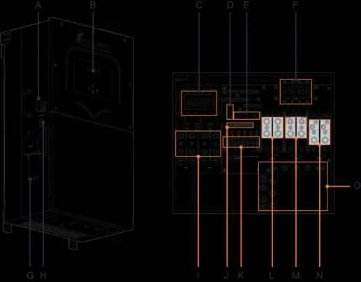
Components and Inputs
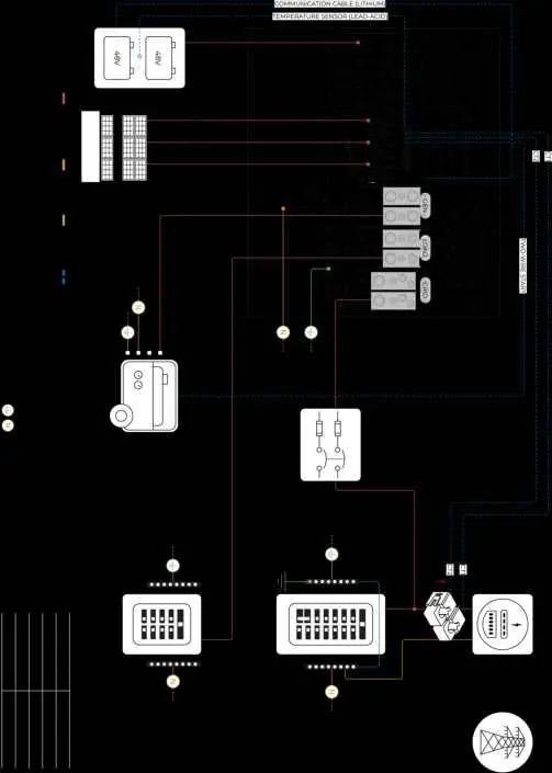
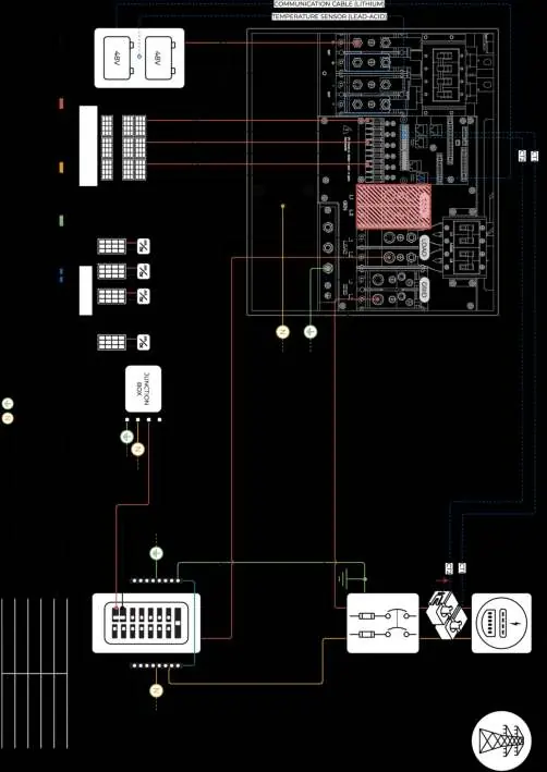
The system includes the inverter, French cleat, filter rings, communication cables, temperature sensor, Wi-Fi/Ethernet dongle, and current transformers (CT sensors). The inverter features multiple inputs including PV DC disconnect, battery breakers, MPPT inputs, and terminals for Grid, Load, and Generator.
Installation
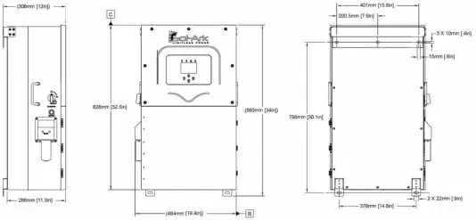
Mounting
Ensure at least 6 inches of vertical clearance and 2 inches of side clearance for heat dissipation. The unit is rated for outdoor installation (NEMA 3R - IP65) but must be protected from direct UV exposure on the LCD screen.
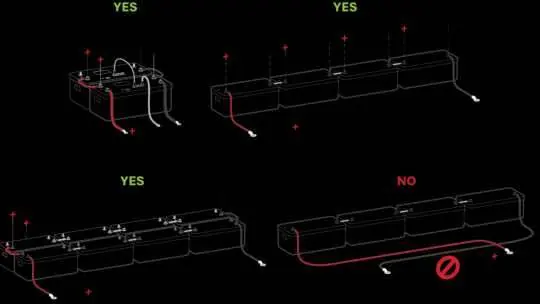
Battery Integration
The system is a 48VDC nominal system. Do not mix battery banks of different makes, models, or chemistry. Ensure the inverter is OFF while connecting batteries. Use both positive and negative terminals for balanced charge/discharge.
PV Modules
The inverter has 3 independent MPPTs supporting up to 2 PV strings each. Maximum VOC is 500V. Strings in parallel on the same MPPT must have the same designed open-circuit voltage.
Generator Integration
Generators smaller than 28.8kW connect to the GEN terminal. Generators larger than 28.8kW connect to the GRID terminal. Ensure the generator has a compatible two-wire start feature if automatic start is required.
System Setup
User Interface
The main screen displays power generation, grid usage, load consumption, and battery status. Use the touch screen to navigate menus for Basic Setup, Battery Setup, Limiter, and Grid Setup.
Limiter and Work Modes
The inverter supports various work modes including Grid Sell, Limited Power to Home (Meter Zero), Limited Power to Load, and Time of Use. These modes determine how generated power is utilized and whether excess power is sold to the grid.
Parallel Systems
For parallel operation, all units must have the same software version. Program one unit as "Master" (Modbus SN: 1) and others as "Slave" (Modbus SN: 2, 3, etc.). Connect communication cables in a daisy-chain configuration.
Troubleshooting
If the system encounters issues, check the System Alarms menu. Common issues include LCD not powering on, DC LED not on, or Grid Phase Wrong errors. Refer to the error codes table for specific fault descriptions and remedies.
Practical help
Common problems
LCD screen not powering on
Ensure at least one power source (PV, Grid, or Battery) is connected and try pressing the power button.
Grid Phase Wrong error
Check wiring phase sequence (AB-BC-CA) and ensure direct rotation (clockwise).
Battery cable sparks when connected
Ensure battery breakers are OFF before connecting or disconnecting batteries.
System beeping
Check the System Alarms menu on the LCD screen to identify the triggered alarm.
Before use
- Verify utility voltage before turning ON.
- Check battery voltage (40V-60V).
- Ensure PV input voltage does not exceed 500V.
- Confirm CT sensors are installed correctly with arrows pointing toward the grid.
- Ensure all wiring is secure and correct.
Specs in practice
- Max. Supported PV Power
- 32,400W
- Continuous Power
- 18,000W
- Nominal DC Voltage
- 48V
- Max. Grid Passthrough Current
- 200A
Images and diagrams
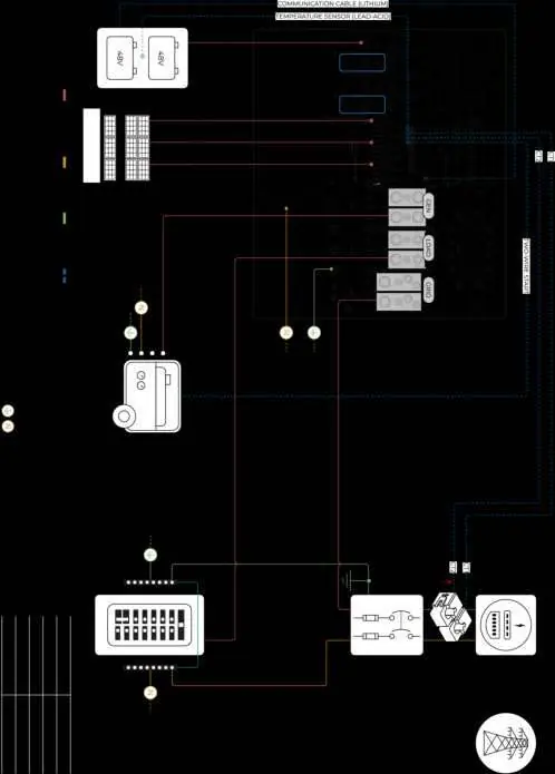
- Standard Wiring Diagram (Diagram 01)
- Line Side Tap (Diagram 02)
- AC Coupling in GEN (Diagram 03)
- AC Coupling in LOAD (Diagram 04)
- Whole-Home Generator (Diagram 05)
Model compatibility
- Compatible with most standard dimmer switches.
- Requires UL 1741SA or UL 1741 certified AC coupled inverters.
- Not compatible with 120V single-phase generators or 120/208V 3-phase generators (2 of 3 phases).

Manual page author
Emily Carter
User documentation editor
Prepares concise manual descriptions and highlights the most useful setup, operation, and maintenance information for readers.