Industrial / Communication Modules
Installation Guide for Solis 1500V PLC CCO
Quick installation and setup guide for the Solis 1500V PLC CCO, covering mounting, cable connections, and technical specifications for PV system integration.
Table of contents
Manual images
Click an image to enlargeQuick guide from the manual
The Solis 1500V PLC CCO is designed for use in PV systems to achieve power line communication, allowing data transmission over AC wires. This document provides essential installation and connection procedures. All operations must be conducted by professional electrical technicians.
Safety and Warnings
- Disconnect all electrical connections and verify no live voltage before installation to prevent electrical hazards.
- Ensure the Inverter AC Switch is in the OFF position.
- Verify the equipment has adequate ventilation.
- Ensure the area of operation is free from strong electromagnetic sources and heat sources.
Package List
Ensure the following items are included in the package:
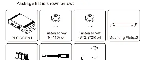
- PLC CCO unit
- 4x Fasten screws (M4*10)
- 4x Fasten screws (ST2.9*25)
- 2x Mounting Plates
- Terminal Plug
- RS485 Communication terminal
- 12V Power Adapter
Installation
The device is designed for hanging installation.
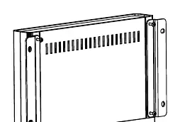
- Use the 4 M4 x 10 cross screws to fix the unit to the wall.
- Ensure the torque value is 1.2Nm.
Cable Connection
Follow these steps to connect the cables:
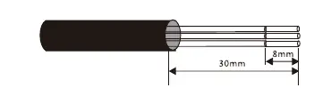
- Stripping: Strip the insulation as shown in the diagram. Remove 30mm of the outer insulation and 8mm of the inner wire.
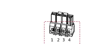
- Terminal Wiring: Use a slot-type screwdriver to press the position in red and insert the A, B, C wires into Pins 1, 2, 3.
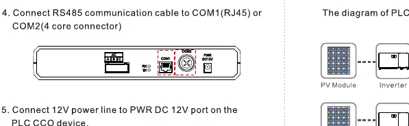
- RS485 Connection: Connect the RS485 communication cable to the COM1 (RJ45) or COM2 (4-core connector) port.
- Power Connection: Connect the 12V power line to the PWR DC 12V port on the device.
Technical Specifications
- Input voltage: 100V AC~240V AC, 50Hz/60Hz
- Power consumption: < 5W
- Operating temperature: -25°C to +70°C
- Protection level: IP20
- Maximum number of PLC STAs: 60pcs
- Maximum transmission rate: 115200bit/s
- Weight: 485g
Practical help
Common problems
System communication failure
Check RS485 wiring connections and ensure the Inverter AC Switch is in the OFF position during installation.
System performance degradation
Ensure the device has adequate ventilation and is not located near strong electromagnetic or heat sources.
Before use
- Verify all electrical connections are disconnected.
- Ensure the Inverter AC Switch is in the OFF position.
- Check that the installation area is free from strong electromagnetic sources.
- Verify no heat sources are near the device.
- Confirm professional electrical technician status for installation.
Specs in practice
- Input voltage
- Supports 100V AC to 240V AC, 50Hz/60Hz.
- Operating temperature
- Device functions between -25°C and +70°C.
- Protection level
- IP20 rating indicates indoor use only, not protected against water.
- Max transmission rate
- 115200bit/s for data communication.
Images and diagrams
- Cable stripping: Strip 30mm of outer insulation and 8mm of inner wire.
- Terminal wiring: Use a slot-type screwdriver to press the terminal positions (1, 2, 3, 4) to insert wires.
Model compatibility
- Supports up to 60 PLC STAs.

Manual page author
David Miller
Documentation analyst
Organizes user manual content into clear summaries, with attention to model details, product context, and everyday usability.