Home Appliances / Space Heaters
User Manual for Somogyi DP 012 2-Flat Wired Doorphone Set
Comprehensive user guide for the Somogyi DP 012 2-Flat Wired Doorphone Set. Includes installation instructions, wiring diagrams, safety warnings, and technical specifications.
Quick answers from the manual
Quick answer
- The Somogyi DP 012 is a 2-flat wired doorphone system. It supports a range of up to 500m using 2x1mm² cables and includes door-opening electronics that do not require additional power. p. 11
Key actions
- Mount indoor units and outdoor unit, route wires, connect to power. p. 3
First start
- Ensure proper wiring according to the schematic diagram, then switch on the electric supply. p. 3
Problems and fixes
Poor sound quality
Use thicker cables (2 x 1 mm²).
p. 4Technical specifications
| Parameter | Value | Meaning | Pages |
|---|---|---|---|
| Range | 500 m | Max range with 2x1mm² cable | p. 11 |
Where to find it in the PDF
- Structure Diagram p. 2
- Installation Guide p. 3
- Safety Instructions p. 4
- Technical Specifications p. 11
Table of contents
Manual images
Click an image to enlargeQuick Guide
The Somogyi DP 012 is a 2-flat wired doorphone system designed to replace conventional doorbells or intercoms. It features a metal outdoor unit and two indoor units. The system supports a range of up to 500 meters when using a 2 x 1 mm² cable. The door-opening electronics do not require additional power supply.
Product Description
The system consists of:
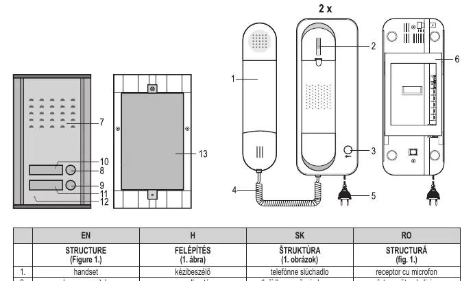
- Indoor Units: Handset with hang-up switch, door opening button, and handset cord.
- Outdoor Unit: Built-in speaker, two call buttons, two replaceable nameplates, and a built-in microphone.
- Mounting: The outdoor unit can be recessed into a wall.
Installation and Wiring
Follow these steps to install the system:
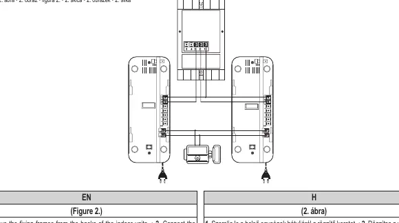
- Remove the fixing frames from the backs of the indoor units.
- Connect the wires to the units according to the schematic diagram.
- Route the wires from the indoor units to the outdoor unit, ensuring they are protected from damage.
- The outdoor unit can be mounted into a chiseled recess in the wall.
- Remove the outdoor unit back cover to connect the wires.
- Connect the door opening electronics to the indoor unit as per the schematic diagram (door opener sold separately).
- Switch on the electric supply.
Safety Warnings
- Mount the device in a location free from vibration.
- Do not place near magnetic fields or electric devices.
- Protect from direct sunlight and precipitation.
- Keep away from ammonia and other harmful gases.
- Disconnect supply voltage if the device is unused for a long period.
- Never attempt to disassemble the device; leave repairs to a professional.
- If the mains cable is damaged, immediately switch off the voltage supply and consult a professional.
Cleaning and Maintenance
Before cleaning, unplug the appliance from the mains outlet. Use a soft, dry cloth for cleaning. Do not use aggressive detergents. The appliance and the mains plug must not be exposed to water.
Technical Specifications
- Power supply: 230 V~ / 50 Hz
- Power consumption: 4.4 W
- Range: Max. 500 m (with 2 x 1 mm² cable)
- Gate opening electronics output: 12 V / 200 mA
- Operating temperature: -30 °C to +50 °C
Disposal
Waste equipment must be collected and disposed of separately from household waste as it may contain hazardous components. Dispose of the product at a facility specializing in the collection of electronic waste. Batteries must not be handled with regular household waste and should be taken to a collection center.
Manufacturer information
Somogyi Elektronic Kft.
Practical help
Common problems
Poor sound quality
Ensure you are using the recommended cable cross-section (2 x 1 mm²). Thin cables may degrade sound quality.
Device not working after long period of inactivity
Check the power supply and ensure all connections are secure.
Before use
- Ensure the mounting location is free from vibration.
- Keep the device away from magnetic fields and electric devices.
- Protect the outdoor unit from direct sunlight and precipitation.
- Ensure cables are routed away from areas where they may be damaged.
- Verify that the cable cross-section is 2 x 1 mm² for optimal range.
Specs in practice
- Power Supply
- Standard 230V AC, 50Hz mains power.
- Gate Opening Output
- 12V DC / 200mA output for controlling an electric door lock.
Images and diagrams
- Figure 1 illustrates the structure of the indoor and outdoor units, identifying the handset, buttons, and nameplates.
- Figure 2 provides the wiring and mounting instructions for the indoor and outdoor units.
Model compatibility
- Suitable for replacing conventional two-wire gate intercom systems.
- The door opener mechanism is not included with the set.

Manual page author
David Miller
Documentation analyst
Organizes user manual content into clear summaries, with attention to model details, product context, and everyday usability.