Toys / RC Models & Drones
Spektrum Firma 130A Brushless Smart Sensored ESC User Manual
Comprehensive user guide for the Spektrum Firma 130A Brushless Smart Sensored ESC (SPMXSE2130S). Includes detailed instructions for installation, wiring, transmitter calibration, programming options, LED status codes, and troubleshooting.
Table of contents
Manual images
Click an image to enlargeQuick Guide from the Manual
The Spektrum Firma 130A Brushless Smart Sensored ESC is a high-performance electronic speed controller designed for 1/8 scale buggies and truggies. Before operating, ensure you have read the safety warnings. The ESC requires proper calibration with your transmitter to function correctly. It supports multiple programming methods, including button programming, the SPMXCA200 Smart Programmer Box, and direct transmitter programming for compatible Spektrum systems.
Installation and Wiring
Follow these steps to install the ESC:
- Mount the ESC and power button using the included mounting tabs or double-sided foam tape in a location with good ventilation.
- Solder the ESC wires (A, B, C) to the corresponding solder tabs on the motor.
- Connect the 6-strand sensor wire from the ESC to the motor.
- Secure all wiring to prevent damage from moving parts.
Notice: Do not connect a dedicated receiver battery to the receiver along with the ESC, as the ESC provides 6V regulated power through the throttle connection.
ESC and Transmitter Calibration
Calibration is essential for proper throttle response:
- Bind your transmitter and receiver.
- Set the throttle channel to 100% travel and trim to neutral.
- Turn on the transmitter and connect the battery to the ESC (do not power on the ESC yet).
- Press and hold the Set button while turning on the ESC. Release the button when the red LED flashes.
- With the throttle at neutral, press the Set button. The green LED will flash once.
- Hold the throttle at full throttle, press the Set button. The green LED will flash twice.
- Hold the throttle at full brake, press the Set button. The green LED will flash three times.
Programming Options
You can customize the ESC using three methods:
- Button Programming: Use the Set button on the switch board to navigate through programming items and values indicated by LED flashes.
- SPMXCA200 Smart Programmer Box: Connect the programming lead to the fan port for a visual interface to change parameters.
- Transmitter Programming: For compatible Spektrum transmitters (e.g., DX5C, DX5R), access the Firma Programming menu directly on the transmitter screen when using a Smart telemetry receiver.
Operation and LED Indicators
To turn on the ESC, leave the transmitter throttle at neutral and press the On/Off button. The motor will emit tones indicating the ESC is operational and the LiPo cell count detected. The LED indicators provide real-time status:
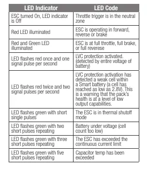
- Red LED illuminated: Operating in forward, reverse, or brake.
- Red and Green LED illuminated: Full throttle, full brake, or full reverse.
- Red LED flashes once: LVC (Low Voltage Cutoff) activated for non-smart battery.
- Green LED flashes: Indicates various errors like thermal shutoff, battery under voltage, or current limit exceeded.
Troubleshooting
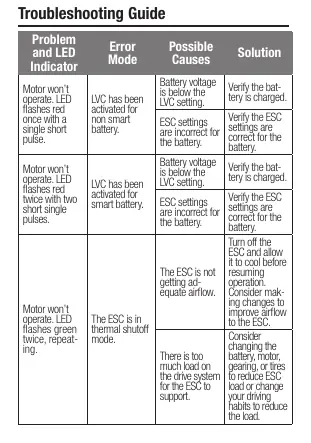
If the motor stutters at start-up, check for poor wiring connections, excessive drag on the drive system, or a faulty sensor wire. If the motor won't operate, check the LED flash codes against the troubleshooting guide to determine if the issue is thermal, voltage-related, or due to incorrect settings.
Manufacturer information
Spektrum
Practical help
Common problems
Motor stutters at start-up
Verify all wiring connections are solid and well-insulated. Check for parts rubbing, bent shafts, or tight gears causing drag. Replace the sensor wire if necessary.
Motor won't operate (Red LED flashes once)
LVC activated for non-smart battery. Verify the battery is charged and ESC settings match the battery type.
Motor won't operate (Green LED flashes twice)
Thermal shutoff mode. Turn off the ESC, allow it to cool, and improve airflow or reduce load.
Motor won't operate (Green LED flashes three times)
Continuous current limit exceeded. Reduce load on the motor or use an ESC with higher current capabilities.
Before use
- Ensure transmitter throttle channel is set to 100% travel and trim is neutral.
- Mount the ESC in a location with adequate ventilation.
- Solder motor wires A, B, and C to the corresponding motor tabs.
- Connect the 6-strand sensor wire.
- Perform the ESC and transmitter calibration procedure.
- Ensure the battery is fully charged.
Specs in practice
- Constant/Peak Current
- 130A / 760A
Images and diagrams
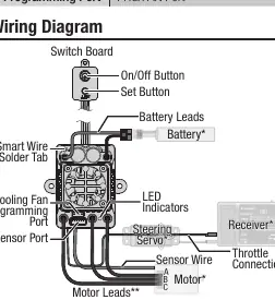
- The wiring diagram illustrates the connection between the Switch Board, Battery, Motor, and Receiver.
- It highlights the location of the Smart Wire Solder Tab, Cooling Fan/Programming Port, and Sensor Port.
Model compatibility
- Compatible with Smart Throttle receivers for telemetry data.
- Requires SPMXCA200 Smart Programmer Box for advanced settings.
- Compatible with Spektrum Smart batteries with IC3 or IC5 connectors for battery data.

Manual page author
Michael Turner
Technical manual editor
Reviews PDF manuals for structure, safety notes, and practical product details so readers can find the right information quickly.