Electronics / USB Hubs & Docking
User Manual for StarTech 2-Port Low-Profile PCIe RS232 Serial Card 21050-PC-SERIAL-LP
Quick-start guide for the StarTech 2-Port Low-Profile PCIe RS232 Serial Card (21050-PC-SERIAL-LP). Includes installation steps, driver setup, jumper configuration for power over Pin 9, and troubleshooting tips.
Quick answers from the manual
Quick answer
- This guide covers the installation and configuration of the StarTech 2-Port Low-Profile PCIe RS232 Serial Card (21050-PC-SERIAL-LP), including hardware setup, driver installation, and power configuration for Pin 9. p. 1, 2
Key actions
- Install the PCI Express Card p. 2
- Install the Driver p. 2
First start
- Power off the computer, insert the card into a PCIe slot, secure the bracket, connect the ribbon cable bracket, and install the drivers. p. 2
Problems and fixes
Serial device not powering
Check J2/J3 jumper settings and J5 power connection.
p. 1, 2Technical specifications
| Parameter | Value | Meaning | Pages |
|---|---|---|---|
| Interface | PCIe 2.0 x1 | Compatible with x1, x4, x8, x16 slots | p. 1 |
| Pin 9 Power | 5V or 12V | Configurable via J3 jumper | p. 1 |
Where to find it in the PDF
- Product Diagrams and Installation p. 1
- Installation Steps and Driver Setup p. 2
Table of contents
Quick guide from the manual
This document provides instructions for the installation and configuration of the StarTech 2-Port Low-Profile PCIe RS232 Serial Card (21050-PC-SERIAL-LP). It covers hardware installation, driver setup, and optional power configuration for Pin 9.
Hardware Installation
- Turn off the host computer and all connected peripheral devices.
- Unplug the power cable from the host computer.
- Disconnect all peripheral devices.
- Remove the computer case cover.
- Locate an open PCI Express slot (x1, x4, x8, or x16) and remove the corresponding slot cover plates.
- Insert the PCIe card into the slot and fasten the bracket to the case.
- Route the ribbon cable bracket to an adjacent expansion slot and fasten it.
- If using a standard tower desktop, replace the pre-installed low-profile brackets with the included full-profile bracket.
- Replace the computer case cover, reconnect the power cable, and reconnect peripheral devices.
- Turn on the host computer.
Power Configuration
The card supports optional power over Pin 9. To configure this:
- J5 Power Connector: Connect a 4-pin SP4/Floppy power connector from the host power supply to the J5 connector on the card.
- J3 Jumper (AUX POWER): Use this to select the voltage output for Pin 9. Set to PCI12V (draws from PCIe slot), AUX12V (12V from J5), or AUX5V (5V from J5).
- J2 Jumpers: Change the jumper caps from DIS (disabled, pins 1-2) to PWR (power, pins 2-3) to enable power output on Pin 9.
Warning: Verify that your serial peripheral device supports the additional voltage on Pin 9 before making changes to avoid equipment damage.
Driver Installation
Windows Systems
- Navigate to www.startech.com/21050-PC-SERIAL-LP and download the driver package from the Drivers & Downloads tab.
- Extract the downloaded zipped file.
- Open the folder corresponding to your Windows version.
- Right-click the Setup file, select Run as administrator, and follow the on-screen instructions.
- Restart the computer if prompted.
Linux Systems
- Run the command lsmod | grep r8125 from the command line to verify the driver is present.
Verification
In Windows, navigate to the Device Manager. Under Ports (COM & LPT), right-click AX99100 PCIe to High Speed Serial Port and select Properties to confirm the driver is installed and working correctly.
Safety Warnings
ESD Warning: PCI Express cards can be damaged by static electricity. Ensure you are properly grounded before opening the computer case. Wear an anti-static strap or touch a grounded metal surface for several seconds before handling the card. Handle the card only by its edges.
Official resources from the manual
Practical help
Common problems
Serial device not powering
Verify that the J2 jumper is set to PWR (pins 2-3) and that the J5 power connector is connected to the host power supply if required.
Card not detected by system
Ensure the card is fully seated in the PCIe slot and that the latest drivers have been installed.
Before use
- Ensure you have an available PCIe slot (x1, x4, x8, or x16).
- Wear an anti-static strap to prevent ESD damage.
- Verify if your serial device requires power over Pin 9.
- Download the latest drivers from the StarTech website.
Specs in practice
- J3 Jumper (AUX POWER)
- Selects voltage (5V or 12V) for Pin 9 power.
Images and diagrams
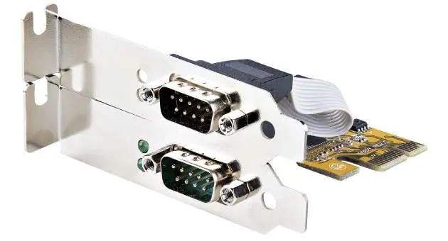
- Diagram 1 shows the card with brackets and ports.
- Diagram 2 highlights the PCB layout, including J2, J3, and J5 connectors.
Model compatibility
- Compatible with PCI Express x1, x4, x8, or x16 slots.
- Requires Windows or Linux operating systems.

Manual page author
David Miller
Documentation analyst
Organizes user manual content into clear summaries, with attention to model details, product context, and everyday usability.