Computers / Storage
User Guide for StarTech 2U 19in Steel Hinged Wall-Mount Bracket
Quick-start guide for the StarTech 2U 19in Steel Hinged Wall-Mount Bracket (WALLMOUNTH2). Includes installation steps, equipment mounting instructions, and product dimensions.
Quick answers from the manual
Quick answer
- This guide provides instructions for installing the StarTech 2U 19in Steel Hinged Wall-Mount Bracket (WALLMOUNTH2) and mounting patch panels. p. 1
Key actions
- Installing the Wall-Mount Bracket p. 1
- Adding Equipment p. 1
- Accessing the Back of a Patch Panel p. 1, 2
Technical specifications
| Parameter | Value | Meaning | Pages |
|---|---|---|---|
| Weight Capacity | 10 kg (22 lb) | Maximum load capacity | p. 1, 2 |
Where to find it in the PDF
- Product Diagram and Installation p. 1
- Dimensions and Warnings p. 2
Table of contents
Manual images
Click an image to enlargeQuick guide from the manual
This document provides installation and usage instructions for the StarTech 2U 19in Steel Hinged Wall-Mount Bracket (model WALLMOUNTH2). It covers mounting the bracket to a wall, installing equipment using cage nuts, and utilizing the hinged side panel for maintenance access.
Package Contents
- Wall-Mount Bracket x 1
- M6 Screws x 4
- M6 Cage Nuts x 4
- Plastic Washers x 4
- M5-25 Flat-head Screws x 4
- Concrete Wall Anchors x 4
- Quick-Start Guide x 1
Installing the Wall-Mount Bracket
Warning: Consult a professional if you lack the expertise to attach this product to the wall. The wall structure must be capable of supporting at least four times the weight of the mounted equipment. Do not add equipment until the bracket is securely attached.
Adding Equipment to the Wall-Mount Bracket
- Insert the wing of an M6 Cage Nut into the back of the desired Cage Nut Hole.
- Apply pressure by hand or with a Cage Nut Tool to insert the second wing.
- Repeat for the desired number of Cage Nuts.
- Thread a Plastic Washer over an M6 Screw.
- Align the Mounting Holes in the equipment with the installed Cage Nuts.
- Insert the assembled screws through the Mounting Holes into the Cage Nuts.
- Tighten the screws using a Phillips Head Screwdriver.
Accessing the Back of a Patch Panel
To access the back of the installed equipment:
- Support the weight of the Patch Panel.
- Use a Phillips Head Screwdriver to unscrew two M6 Screws from the Cage Nuts, leaving the other two attached to the side with the Hinged Side Panel.
- Gently swing the Patch Panel away from the Wall-Mount Bracket.
- Reattach the two M6 Screws after accessing the back.
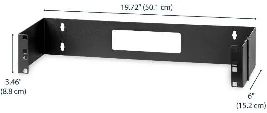
Product Dimensions
The bracket measures 19.72" (50.1 cm) in width, 3.46" (8.8 cm) in height, and 6" (15.2 cm) in depth.
Practical help
Common problems
Equipment not fitting
Ensure the equipment is 2U or smaller and compatible with M6 cage nuts.
Wall mounting issues
Ensure the wall structure can support at least four times the weight of the mounted equipment.
Before use
- Phillips Head Screwdriver
- Optional Cage Nut Tool
- Verify wall structure can support 4x the equipment weight
Specs in practice
- Weight Capacity
- Maximum 10 kg (22 lb)
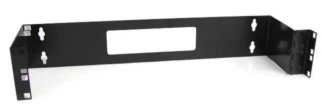
Images and diagrams
- Mounting Holes: Used to mount the bracket to a wall.
- Cage Nut Holes: Used to mount a Patch Panel in the bracket.
- Hinged Side Panel: Used to access the back of the installed Patch Panel.
Model compatibility
- Designed for 19-inch rack-mount equipment
- Maximum height 2U

Manual page author
David Miller
Documentation analyst
Organizes user manual content into clear summaries, with attention to model details, product context, and everyday usability.