Electronics / Cables & Adapters
User Guide for StarTech 1P3FFCNB-USB-SERIAL USB to Null Modem Serial Adapter Cable
Quick-start guide for the StarTech USB to Null Modem Serial Adapter Cable. Includes driver installation steps for Windows and macOS, pinout diagrams, and verification procedures.
Quick answers from the manual
Quick answer
- This guide provides instructions for installing the StarTech USB to Null Modem Serial Adapter Cable, including driver installation for Windows and macOS, and verification steps. p. 1, 2
Key actions
- Install drivers p. 1
- Verify driver installation p. 2
First start
- Connect the adapter to a USB-A port after installing the necessary drivers. p. 1
Problems and fixes
Drivers do not install automatically
Download the driver package from the StarTech support website and run the setup file.
p. 1Technical specifications
| Parameter | Value | Meaning | Pages |
|---|---|---|---|
| Pin 1 | DCD | Data Carrier Detect | p. 1 |
| Pin 2 | TXD | Transmit Data | p. 1 |
| Pin 3 | RXD | Receive Data | p. 1 |
Where to find it in the PDF
- Quick-Start Guide p. 1, 2
Table of contents
Manual images
Click an image to enlargeQuick guide from the manual
This document provides instructions for the StarTech USB to Null Modem Serial Adapter Cable. It covers driver installation, hardware connection, and verification steps for Windows and macOS systems.
Package Contents
- USB to Serial Adapter x 1
- DB9 Nuts x 2
- Quick-Start Guide x 1
Requirements
To use this adapter, you need a computer with an available USB Type-A port. Drivers should install automatically on most supported operating systems.
Installation
If drivers do not install automatically, follow these steps:
- Navigate to the product support page on the StarTech website (www.StarTech.com/1P3FFCNB-USB-SERIAL or www.StarTech.com/1P10FFCN-USB-SERIAL).
- Click the Drivers/Downloads tab.
- Download the appropriate Driver Package for your operating system.
Windows Installation
- Right-click the downloaded file and extract the contents using Extract All.
- Browse the Windows folder and run the Setup file.
- Follow the on-screen instructions to complete the installation.
- Connect the USB to Serial Adapter to an available USB-A port.
macOS Installation
- Double-click the downloaded file.
- Open the folder that matches your macOS version and run the Installer file inside the folder.
- Follow the on-screen instructions to complete the installation.
- Connect the USB to Serial Adapter to an available USB-A port.
Verifying Driver Installation
Windows
- Navigate to the Device Manager.
- Under Ports (COM & LPT), right-click COM Port and select Properties.
- Confirm that the driver is installed and working as expected.
macOS
- Navigate to System Information.
- Expand the Hardware section and click USB.
- Confirm that the COM Port appears in the list.
Component Overview
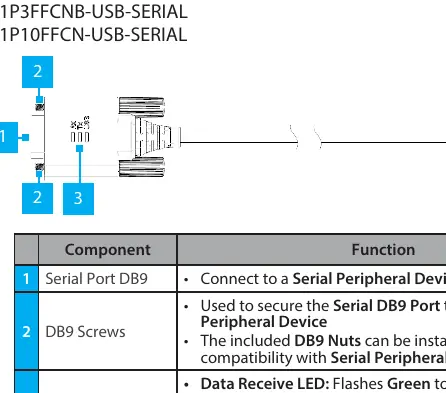
- Serial Port DB9: Connects to a Serial Peripheral Device.
- DB9 Screws: Used to secure the Serial DB9 Port to the peripheral device.
- LED Indicators:
- Data Receive LED: Flashes Green to indicate activity.
- Data Transmit LED: Flashes Yellow to indicate activity.
- USB LED: Solid Blue indicates driver is installed and USB connection is enumerated.
- USB Type A Port: Connects the adapter to the computer.
Pinout Diagram
The adapter uses a standard RS-232 pin configuration:
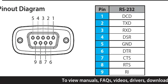
- Pin 1: DCD
- Pin 2: TXD
- Pin 3: RXD
- Pin 4: DSR
- Pin 5: GND
- Pin 6: DTR
- Pin 7: CTS
- Pin 8: RTS
- Pin 9: RI
Official resources from the manual
Practical help
Common problems
Drivers do not install automatically
Visit the StarTech support website, download the driver package for your OS, and manually run the setup or installer file.
Before use
- Ensure you have a computer with an available USB Type-A port.
- Identify the serial peripheral device to be connected.
- Download the latest drivers from the StarTech support website if automatic installation fails.
Specs in practice
- Data Receive LED
- Flashes Green to indicate activity.
- Data Transmit LED
- Flashes Yellow to indicate activity.
Images and diagrams
- The pinout diagram shows the 9-pin configuration for RS-232 communication.
- The component diagram identifies the Serial Port DB9, DB9 Screws, LED indicators, and USB Type-A connector.
Model compatibility
- Requires a USB Type-A enabled computer.
- Compatible with serial peripheral devices.

Manual page author
David Miller
Documentation analyst
Organizes user manual content into clear summaries, with attention to model details, product context, and everyday usability.