Automotive / Car Audio
User Manual for Stetsom 1K2 Digital Amplifier
Comprehensive user guide for the Stetsom 1K2 Digital Amplifier. Includes detailed installation instructions, wiring diagrams, safety precautions, troubleshooting steps, and technical specifications.
Quick answers from the manual
Quick answer
- The Stetsom 1K2 is a digital amplifier. Installation requires a 70A fuse, 6 AWG power cables, 18 AWG remote cable, and 11 AWG speaker cables. Ensure all connections are made with the unit powered off. p. 2, 6
Key actions
- Install a 70A fuse as close to the battery as possible. p. 6
- Adjust the LEVEL control to prevent distortion. p. 8
First start
- Ensure all connections are made with the product turned OFF. p. 2
Problems and fixes
PROT LED flashing
Check for short circuits, overheating, or voltage issues (below 9V or above 17V).
p. 5Maintenance and reset
- If the amplifier enters protection mode, verify the problem and turn the amplifier on again. p. 5
Technical specifications
| Parameter | Value | Meaning | Pages |
|---|---|---|---|
| Supply Voltage | 9V - 17V DC | Operating voltage range | p. 9 |
| Fuse | 70A | Required fuse rating | p. 6 |
Where to find it in the PDF
- Controls and Inputs p. 3
- Installation Diagram p. 6
- Troubleshooting p. 7
- Technical Specifications p. 9
Table of contents
Manual images
Click an image to enlargeQuick Guide from the Manual
The Stetsom 1K2 is a high-performance digital amplifier. Before installation, ensure the product is turned OFF. A 70A fuse must be installed as close to the battery as possible to protect against overcurrent. Installation should only be performed by a qualified professional.
Device Overview
The amplifier features the following controls and inputs:
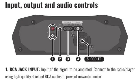
- RCA JACK INPUT: Connect to your radio/player using high-quality shielded RCA cables.
- LEVEL: Adjusts the input signal level.
- CROSSOVER: Includes a Subsonic filter (8Hz-40Hz) and a Low Pass Filter (30Hz-250Hz).
- BASS BOOST: Adjusts bass intensity (0dB to +10dB) and frequency (30Hz-70Hz).
- COOLER: Integrated cooling system; ensure air vents are not obstructed.
Installation
Proper installation is critical for performance and safety. Use the following cable specifications:
- Power Connectors (Positive/Negative): 6 AWG (13mm²)
- Remote Connector: 18 AWG (0.75mm²)
- Output Signal Connectors (Speakers): 11 AWG (4mm²)
- Fuses/Circuit Breakers: 70A
Route installation cables away from the vehicle's original wiring to prevent interference. Ensure a solid ground connection by removing paint from the vehicle chassis at the grounding point.
LED Indicators and Protection
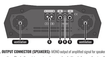
The amplifier features three LEDs:
- POWER (Blue): Indicates the amplifier is on.
- PROT (Red): Indicates a malfunction or protection mode.
- CLIP (Red): Indicates signal distortion.
If the PROT LED blinks, refer to the diagnostic table:
- 1x Blink: Short circuit or output overload. Check speaker cables and impedance.
- 2x Blinks: Excessive temperature (approx. 194°F/90°C). Ensure proper ventilation.
- 3x Blinks: Supply voltage less than 9V. Check battery/power supply.
- 4x Blinks: Supply voltage greater than 17V. Check battery/power supply.
Troubleshooting
If you encounter issues, follow these steps:
- Amplifier does not turn on: Verify cable connections, check fuses, and ensure the battery is charged.
- No sound: Check RCA and speaker connections; ensure the LEVEL control is not set to minimum.
- Sound distortion: Lower the LEVEL control and readjust. Play a musical signal at 80% volume on the radio, then increase the amplifier LEVEL until the CLIP LED flashes, then back it off until the LED turns off.
- Weak Bass: Check for reversed speaker polarity (out-of-phase).
Practical help
Common problems
Amplifier does not turn on
Verify all cable connections for electrical and mechanical contact. Check if fuses or circuit breakers are blown and ensure the battery is sufficiently charged.
No sound
Ensure speaker cables and RCA plugs are connected correctly. Verify that the LEVEL control is not set to minimum.
PROT LED flashing
Check for short circuits, blocked air vents (overheating), or supply voltage issues (below 9V or above 17V).
Sound distortion
Lower the LEVEL control and readjust. Ensure speakers are not overloaded.
Before use
- Ensure the product is turned OFF before making any connections.
- Install a 70A fuse as close to the battery as possible.
- Use 6 AWG cables for power, 18 AWG for remote, and 11 AWG for speakers.
- Verify the minimum impedance supported by the amplifier.
- Ensure the installation location is firm, dry, and well-ventilated.
- Route cables away from original vehicle wiring to avoid interference.
Specs in practice
- Subsonic Filter
- Selects the initial frequency (8Hz-40Hz) reproduced by the amplifier.
- Low Pass Filter (L.P.F.)
- Selects the final frequency (30Hz-250Hz) reproduced by the amplifier.
Images and diagrams
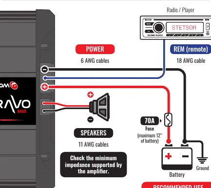
- Wiring diagram illustrates the connection between the Radio/Player, Amplifier, and Battery.
- Shows the mandatory placement of the 70A fuse near the battery.
- Indicates the connection points for Power, Remote, and Speakers.
Model compatibility
- Requires 9V-17V DC power supply.
- Minimum output impedance varies by model (1 Ohm or 2 Ohm versions).

Manual page author
Emily Carter
User documentation editor
Prepares concise manual descriptions and highlights the most useful setup, operation, and maintenance information for readers.