Lighting / Outdoor Lighting
Sunco Lighting 120W Wall Pack User Manual
Comprehensive installation guide and user manual for the Sunco Lighting 120W Wall Pack. Includes detailed wiring instructions for junction box and direct mount installations, J-Box compatibility requirements, safety warnings, and technical...
Table of contents
Manual images
Click an image to enlargeQuick guide from the manual
This document provides installation instructions for the Sunco Lighting 120W Wall Pack. Before beginning, ensure the power is turned off at the fuse or circuit breaker. The fixture supports two installation methods: Junction Box installation and Direct Mount with Conduit. Always verify compatibility with your existing junction box before starting.
Components
The package includes the following items:
- 3x Screws
- 3x Wall Anchors
- 3x Wire Nuts
- 1x Trim Plate
- 1x Attached Level
- 1x Attached Rubber Gasket
Junction Box Installation
- Turn off power at the fuse or circuit breaker.
- Open the cover by unscrewing the 2 door screws on the side of the wall pack and lift off the pinned hinges. Disconnect the TP24 connector if connected.
- Drill 2 holes in the base plate to match the J-Box holes.
- Use the internal level to position the wall pack on the wall.
- Slide the trim plate between the wall and the back plate. Pull supply wires through the center hole.
- Align 2 holes in the base plate with the junction box and secure with 2 screws.
- Connect internal wires to the power supply using 3 wire nuts (Live to Black, Neutral to White, Ground to Yellow/Green).
- Seal 3 open holes with waterproofing material (caulk not included).
- Slide the cover onto the base plate, connect the TP24 connector, and secure the cover with 2 door screws. Ensure no wiring is pinched.
- Turn ON power to verify installation.
Direct Mount with Conduit Installation
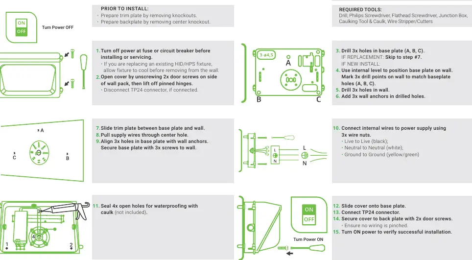
- Turn off power at the fuse or circuit breaker.
- Open the cover by unscrewing the 2 door screws and lift off the pinned hinges.
- Drill 3 holes in the base plate (A, B, C).
- Use the internal level to position the base plate on the wall. Mark 3 drill points on the wall to match baseplate holes.
- Drill 3 holes in the wall and insert 3 wall anchors.
- Slide the trim plate between the base plate and the wall. Pull supply wires through the center hole.
- Align 3 holes in the base plate with wall anchors and secure with 3 screws.
- Connect internal wires to the power supply using 3 wire nuts (Live to Black, Neutral to White, Ground to Yellow/Green).
- Seal 4 open holes with waterproofing material (caulk not included).
- Slide the cover onto the base plate, connect the TP24 connector, and secure the cover with 2 door screws. Ensure no wiring is pinched.
- Turn ON power to verify installation.
J-Box Compatibility
This fixture is compatible with 4-inch octagon, square, or round junction boxes, as well as 3.5-inch round new work or old work junction boxes. The base plate includes 8 potential drilling holes. The outside circle has a 3.54 inch (90mm) distance between holes, and the inner circle holes are 2.76 inches (70mm) apart.
Specifications
- Voltage: 120-277V
- Wattage: 120W
- Current: 1/0.44A
- Power Factor: 0.97
- Lumens: 12000
- Color Temperature: 5000K
- Color Rendering Index (CRI): 80
- Beam Angle: 110 degrees
Safety Warnings
- This product must be installed in accordance with applicable installation codes by a person familiar with the construction and operation of the product.
- Abide by all regional and local laws or regulations.
- Proper grounding is required to ensure safety.
- Check for damage during shipping prior to installation. Do not use if damaged.
- Turn off the switch and circuit breaker before installing.
- Use safety precautions, including safety eyeglasses and gloves.
Practical help
Common problems
Wiring pinched during cover installation
Ensure all wires are tucked neatly inside the base plate before securing the cover with door screws.
Water ingress
Ensure all open holes in the base plate are sealed with waterproofing material (caulk) as specified in the installation steps.
Fixture does not fit junction box
Verify compatibility: supports 4" octagon/square/round and 3.5" round new/old work boxes. Check hole spacing (3.54" outer, 2.76" inner).
Before use
- Turn off power at the fuse or circuit breaker.
- Inspect the fixture for damage during shipping.
- Gather required tools: Drill, Philips Screwdriver, Flathead Screwdriver, Junction Box, Caulking Tool & Caulk, Wire Stripper/Cutters.
- Prepare trim plate by removing knockouts.
- Prepare backplate by removing center knockout.
- Wear safety eyeglasses and gloves.
Specs in practice
- Color Temperature
- 5000K provides a daylight white light appearance.
Images and diagrams
- The manual provides specific diagrams for both Junction Box and Direct Mount installation methods.
- Wiring diagram shows standard color coding: Black (Live), White (Neutral), Yellow/Green (Ground).
Model compatibility
- Compatible with 4" octagon, square, and round junction boxes.
- Compatible with 3.5" round new work and old work junction boxes.

Manual page author
Michael Turner
Technical manual editor
Reviews PDF manuals for structure, safety notes, and practical product details so readers can find the right information quickly.