Power / Solar Inverters
User Manual for Sungrow 1-phase Hybrid Inverter SH3.0RS - SH6.0RS
Comprehensive user manual for the Sungrow 1-phase Hybrid Inverter series (SH3.0RS, SH3.6RS, SH4.0RS, SH5.0RS, SH6.0RS). This guide covers installation, electrical wiring, system commissioning, iSolarCloud app configuration, and...
Table of contents
Manual images
Click an image to enlargeQuick guide from the manual
This manual provides essential information for the installation, operation, and maintenance of the Sungrow 1-phase Hybrid Inverter. Professional technicians must perform the installation, ensuring compliance with local electrical standards. Key steps include mechanical mounting, electrical connection (AC, DC, Battery, and Communication), and system commissioning via the iSolarCloud App.
Product Description
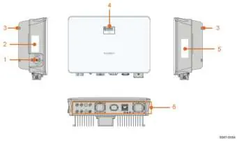
The inverter is a transformerless 1-phase hybrid unit designed to convert DC power from PV modules or batteries into grid-compatible AC power. It supports both on-grid and off-grid applications. The front panel features an LED indicator for status monitoring and an optional DC switch for safety.
Mechanical Mounting
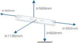
The inverter must be installed vertically in a well-ventilated area. Ensure the installation surface can support four times the weight of the inverter. Maintain specific clearances for heat dissipation: at least 500mm above, 300mm on sides, 1000mm in front, and 400mm below.
Electrical Connection
Electrical connections must be performed by professionals. Key connections include:
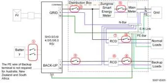
- External Protective Grounding: Must be connected before any other electrical work.
- AC Cable: Connect to the GRID and BACKUP terminals. An independent AC circuit breaker is required.
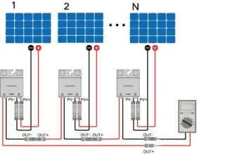
- DC Cable (PV): Connect PV strings to the MC4 terminals. Ensure correct polarity.
- Battery: Connect power cables and communication cables (CAN/RS485) according to the battery manufacturer's instructions.
- Communication: Ports include RS485, Ethernet, WLAN, and CAN for system monitoring.
Commissioning
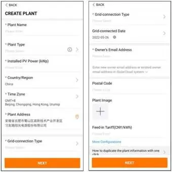
Before commissioning, verify all installations and ensure the DC switch and AC circuit breaker are OFF. Use the iSolarCloud App to create a plant, bind the device, and configure network settings. The inverter will start automatically once grid and irradiation conditions are met.

iSolarCloud App
The app allows for remote monitoring, data logging, and maintenance. Users can perform initial settings, firmware updates, and configure power regulation parameters (Active/Reactive Power) through the app.
Troubleshooting and Maintenance
If a fault occurs, the app displays the fault code. Common issues include grid overvoltage/undervoltage, PV reverse connection, and insulation resistance faults. Routine maintenance includes checking for dust, ensuring cable connections are firm, and verifying the general status of the system every 6 months.
Practical help
Common problems
Grid Overvoltage (Alarm ID 2, 3, 14, 15)
Measure actual grid voltage. If higher than the set value, contact the local electric power company. Check protection parameters via the App.
Grid Undervoltage (Alarm ID 4, 5)
Measure actual grid voltage. If lower than the set value, contact the local electric power company. Check if the AC cable is firmly connected.
PV Reverse Connection (Alarm ID 28, 29, etc.)
Check string polarity. Disconnect the DC switch and adjust polarity when string current is below 0.5A.
Low System Insulation Resistance (Alarm ID 39)
Check resistance to ground of the string and DC cable. Check for damaged insulation or short circuits.
Excessively High Ambient Temperature (Alarm ID 37)
Ensure the inverter is in a well-ventilated place, not exposed to direct sunlight, and the fan is running properly.
Before use
- Ensure all equipment is reliably installed.
- Verify that DC switch(es) and AC circuit breaker are in the OFF position.
- Confirm the ground cable is properly and reliably connected.
- Check that AC and DC cables are properly and reliably connected.
- Ensure communication cables are properly connected.
- Verify that all vacant terminals are sealed.
- Ensure all warning signs and labels are intact and legible.
Specs in practice
- Max. PV input voltage
- 600V. Do not exceed this limit.
- Max. charge/discharge current
- 30A. Limits the battery power flow.
- Degree of protection
- IP65. Suitable for both indoor and outdoor installation.
- Operating ambient temperature
- -25°C to 60°C. Inverter will derate in high temperatures.
Images and diagrams
- Wiring diagrams are provided for different grid types (TT, TN-C, TN-S, TN-C-S).
- The terminal layout shows the location of PV, Battery, AC, and Communication ports at the bottom of the inverter.
Model compatibility
- Compatible with Li-ion batteries from SUNGROW and BYD.
- Not suitable for supplying power to life-sustaining medical devices.
- SUNGROW inverters cannot be used with third-party optimizers.

Manual page author
Michael Turner
Technical manual editor
Reviews PDF manuals for structure, safety notes, and practical product details so readers can find the right information quickly.