Lighting / Controllers & Dimmers
Sunricher 0-10V Fixture-integrated Sensor-less Controller SR-IG9032A-V User Guide
Quick guide for the Sunricher SR-IG9032A-V 0-10V controller. Includes wiring instructions, reset procedures, technical specifications, and safety warnings.
Table of contents
Manual images
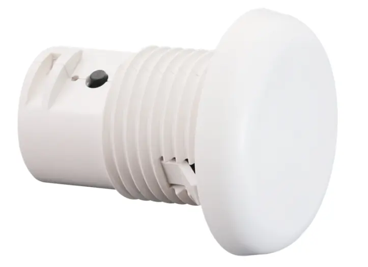
Click an image to enlargeQuick guide from the manual
The Sunricher SR-IG9032A-V is a fixture-integrated controller designed for 0-10V signal conversion and Wirepas mesh networking. To operate the device, ensure correct wiring according to the provided diagram. To reset the device, press and hold the reset button for over 5 seconds until the indicator flashes. Always ensure power is disconnected before installation.
Product Overview
The SR-IG9032A-V acts as a 0-10V signal converter within a Wirepas mesh network. It features a built-in 20mA 0-10V signal output and supports broadcast control for all devices on the 0-10V line. The device is compatible with kinetic energy switches and EnOcean switches (EWSSB and EWSDB). It includes an on-board antenna and is rated IP20 for indoor use.
Technical Specifications

- Input Power: 12-24VDC
- Signal: Wirepas (INGY)
- Output: 0/1-10V, Max 20mA
- Dimming Curve: Logarithmic
- Dimming Method: PWM
- Operating Temperature: 0°C to 45°C
- Relative Humidity: 8% to 80%
Installation and Wiring
The device must be wired according to the connection diagram. Ensure the power supply (12/24V CV PSU) is connected correctly to the V+ and GND terminals. The 0-10V dimmable driver connects to the DIM+ and GND ports. Note that V+ is the power supply, GND is the common port for V- and Dim-, and DIM+ represents the 0-10V signal port.
Operation
The controller supports manual control and In-node Scheduling (INS). To withdraw the device from the internet or app, use the Reset Key. Pressing the reset button for more than 5 seconds will trigger a reset, indicated by the LED flashing quickly.
Safety and Compliance
Warning: Do not install the device while power is applied. Do not expose the device to moisture. The device is FCC and IC compliant, designed for residential installation with protection against harmful interference.
Practical help
Common problems
Device needs to be removed from the network/app
Press and hold the Reset Key on the controller for over 5 seconds until the LED flashes.
Wireless communication range issues
Typical range is 20m to 25m in indoor environments; actual range depends on field installation.
Before use
- Ensure power is disconnected before starting installation.
- Verify the power supply is 12-24VDC.
- Confirm compatibility with 0-10V dimmable drivers.
- Check that the installation environment is within 0°C to 45°C.
- Ensure the location is dry (IP20 rating).
Images and diagrams
- The wiring diagram illustrates the connection between the 12/24V CV PSU, the controller, and the 0-10V dimmable driver.
- V+ connects to the positive power supply.
- GND serves as the common port for V- and Dim-.
- DIM+ connects to the 0-10V signal port of the driver.
Model compatibility
- Compatible with kinetic energy switches.
- Compatible with EnOcean switches (EWSSB and EWSDB).

Manual page author
David Miller
Documentation analyst
Organizes user manual content into clear summaries, with attention to model details, product context, and everyday usability.