Lighting / Controllers & Dimmers
User Manual for SuperLightingLED DL 4-Channel DMX512 Decoder
Quick start guide and operation manual for the SuperLightingLED DL 4-Channel DMX512 Decoder. Learn how to configure DMX modes, set parameters, wire the device, and troubleshoot common issues.
Quick answers from the manual
Quick answer
- This manual provides instructions for installing, wiring, and configuring the SuperLightingLED DL 4-Channel DMX512 Decoder, including DMX address setup, stand-alone mode operation, and troubleshooting. p. 1, 2
Key actions
- Wiring the decoder p. 1
- Setting DMX address p. 2
- Configuring system parameters p. 2
First start
- Automatic DMX mode entry p. 2
Problems and fixes
No light
Check the power; check the connection.
p. 2
Wrong color
Reconnect 0-10V output wires; set correct decode address.
p. 2Maintenance and reset
- Restore factory default parameters p. 2
Technical specifications
| Parameter | Value | Meaning | Pages |
|---|---|---|---|
| Input voltage | 12-24VDC | Operating voltage range | p. 1 |
| Output signal | 0/1-10V analog | Control signal type | p. 1 |
| Output current | 4CH, 20mA/CH | Maximum current per channel | p. 1 |
| IP rating | IP20 | Ingress protection rating | p. 1 |
| Operation temperature | -30°C ~ +55°C | Ambient operating temperature range | p. 1 |
| Warranty | 5 years | Warranty period | p. 1 |
Where to find it in the PDF
- Features, Technical Parameters, and Wiring p. 1
- Operation, Modes, and Troubleshooting p. 2
Table of contents
Manual images
Click an image to enlargeQuick Guide from the Manual
The SuperLightingLED DL is a 4-channel DMX512 decoder designed for professional lighting control. It supports RDM functions, 0-10V/1-10V output, and various stand-alone modes. This device is intended for indoor use and requires proper wiring to DMX masters and LED drivers.
Technical Specifications
The device operates within the following parameters:
- Input Voltage: 12-24VDC
- Input Signal: DMX512
- Output Signal: 0/1-10V analog
- Output Current: 4CH, 20mA/CH
- Operating Temperature: -30°C to +55°C
- IP Rating: IP20
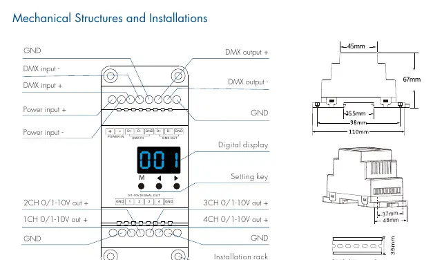
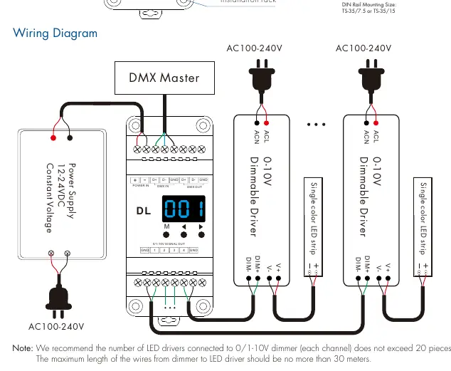
Wiring and Installation
The decoder is designed for DIN rail mounting (TS-35/7.5 or TS-35/15). Ensure all connections are secure before powering on. The wiring diagram illustrates the connection from the DMX Master to the decoder, and from the decoder to the dimmable drivers. Note that the maximum length of wires from the dimmer to the LED driver should not exceed 30 meters, and it is recommended not to exceed 20 LED drivers per channel.
System Parameter Settings
To enter system parameter settings, long press the M and Left keys for 2 seconds. Use the M key to switch between items:
- Decode Mode: Select 1-channel (d-1), 2-channel (d-2), or 4-channel (d-4) decode.
- 0/1-10V Output: Switch between 0-10V (0-0) or 1-10V (1-0).
- Output Brightness Curve: Switch between linear (C-L) or logarithmic (C-E).
- Default Output Level: Set 0-100% level (d00 to dFF) when no DMX signal is present.
- Automatic Blank Screen: Enable (bon) or disable (boF).
Long press M for 2 seconds or wait 10 seconds to exit.
DMX Mode
Short press the M key until the display shows 001-512 to enter DMX mode. Use the Left or Right keys to change the DMX decode address. The device will automatically enter DMX mode if a DMX signal is detected.
Stand-alone RGB/RGBW Mode
Short press the M key until the display shows P01-P24 to enter this mode. Use the Left or Right keys to change the dynamic mode number. Long press M for 2 seconds to adjust speed, brightness, and W channel brightness. Short press M to switch between these items.
Stand-alone Dimmer Mode
Short press the M key until the display shows L-1 to L-8 to enter this mode. Use the Left or Right keys to change the dimmer mode number. Long press M for 2 seconds to adjust the brightness of each channel independently.
Dimming Curve Settings
The device supports both linear and logarithmic dimming curves. These can be configured in the system parameter settings to adjust how the output voltage responds to brightness input.
Troubleshooting
If you encounter issues, check the following:
- No light: Check the power supply and ensure all connections are secure.
- Wrong color: Verify the 0-10V output wire connections and ensure the DMX decode address is set correctly.
Practical help
Common problems
No light
Check the power supply and ensure all connections are secure.
Wrong color
Check the 0-10V output wire connections and ensure the DMX decode address is set correctly.
Before use
- Verify input voltage is 12-24VDC.
- Ensure DMX signal source is compatible with DMX512 protocol.
- Check wiring polarity for Power IN and DMX IN/OUT.
- Confirm LED driver compatibility (max 20 drivers per channel).
- Ensure wire length from dimmer to LED driver is under 30 meters.
Specs in practice
- Input voltage
- 12-24VDC required for operation.
- Output signal
- 0/1-10V analog signal for controlling dimmable drivers.
Images and diagrams
- Wiring diagram shows connection from DMX Master to Decoder, and from Decoder to Dimmable Drivers.
- Mechanical structure shows DIN rail mounting dimensions (TS-35/7.5 or TS-35/15).
Model compatibility
- Compatible with DMX512 standard protocols.
- Supports RDM function for intercommunication.
- Max wire length from dimmer to LED driver is 30 meters.

Manual page author
David Miller
Documentation analyst
Organizes user manual content into clear summaries, with attention to model details, product context, and everyday usability.