Lighting / Controllers & Dimmers
User Manual for Rayrun T122 2-Wire CCT LED Controller
Quick guide for the Rayrun T122 2-Wire CCT LED Controller. Includes wiring diagrams, remote pairing instructions, brightness and color temperature adjustment, and technical specifications.
Quick answers from the manual
Quick answer
- The Rayrun T122 is a 2-wire CCT LED controller that operates on 5-24V DC. It allows for brightness and color temperature adjustment via an RF remote. p. 1
Key actions
- Pairing a new remote p. 4
First start
- Remove battery insulation tape and connect power supply to input, LED loads to output. p. 1, 4
Problems and fixes
Remote indicator flashes slowly
Replace the CR2032 battery.
p. 4Where to find it in the PDF
- Introduction and Wiring p. 1
- Remote Operation and Specs p. 4
Table of contents
Manual images
Click an image to enlargeQuick guide from the manual
The Rayrun T122 is a constant voltage LED controller designed for 2-wire tunable white (CCT) LED products. It operates on a DC voltage range of 5V to 24V. The system consists of a receiver and an RF remote controller used to adjust brightness and color temperature.
Wiring and installation
Before installation, ensure the power supply voltage matches the LED load's rated voltage. The controller output voltage is the same as the power input voltage.
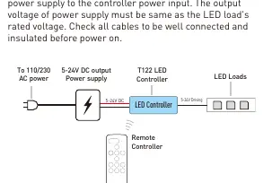
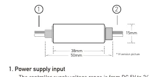
- Power Input: Connect the DC power supply to the controller input. Observe the polarity markings on the controller.
- LED Output: Connect the LED loads to the output terminals. Ensure correct polarity.
- Safety: Ensure all cables are well insulated to prevent short circuits, which can permanently damage the controller. Do not install the controller in closed metal parts, as this may block the RF signal.
Remote controller operation
Before using the remote, pull out the battery insulation tape. The remote uses a CR2032 battery.
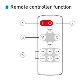
- Turn ON/OFF: Press the 'I' key to turn on and the 'O' key to turn off. The controller memorizes the status and restores it upon the next power-on.
- Adjustments: Use the brightness keys to increase or decrease intensity. Use the color temperature keys to adjust the white balance.
- Shortcuts: Use the shortcut keys to jump to specific brightness or color temperature settings.
Pairing a new remote controller
The receiver and remote are paired 1-to-1 by default. You can pair up to 5 remotes to one receiver.
- Disconnect the power from the receiver and wait for more than 5 seconds.
- Reconnect the power.
- Within 10 seconds of powering on, press the color temperature keys simultaneously for about 3 seconds.
- The LED fixture will flash quickly to confirm successful pairing.
To clear other remotes and keep only the current one, simply re-pair the current remote to the receiver.
Overheat protection
The controller features built-in overheat protection. If the unit overheats due to overloading or abnormal usage, it will automatically shut down the output. It will recover once the temperature drops to a safe range.
Technical specifications
- Working Voltage: DC 5-24V
- Rated Output Current: 3A
- Remote Frequency: 433.92MHz
- Control Distance: >15m in open area
- PWM Frequency: 1KHz
- Dimensions: 50 x 15 x 7 mm
Practical help
Common problems
Remote controller not responding
Check if the battery insulation tape is removed. If the indicator flashes slowly when pressing keys, replace the CR2032 battery.
Controller overheating
Ensure the load current is within the 3A rated limit. Check for short circuits in the wiring.
Poor remote signal reception
Do not install the controller inside closed metal parts, as metal blocks RF signals.
Before use
- Verify the power supply voltage (5-24V DC) matches the LED load voltage.
- Ensure all cables are securely connected and insulated.
- Check the polarity markings on the controller before connecting power and LED loads.
- Remove the battery insulation tape from the remote control.
Specs in practice
- Working Voltage
- The controller accepts DC input between 5V and 24V.
- Rated Output Current
- The maximum current the controller can handle is 3A.
- Remote Frequency
- Operates on 433.92MHz RF frequency.
Images and diagrams
- The wiring diagram illustrates connecting the AC power to the DC power supply, then to the controller input, and finally to the LED loads.
- The remote controller diagram identifies the power buttons, brightness adjustment keys, and color temperature adjustment keys.
Model compatibility
- Designed for 2-wire tunable white (CCT) constant voltage LED products.
- Not compatible with AC voltage inputs.

Manual page author
David Miller
Documentation analyst
Organizes user manual content into clear summaries, with attention to model details, product context, and everyday usability.