Home / Door Hardware
Installation Instructions for TownSteel 2023-A Mortise Device
A comprehensive installation guide for the TownSteel 2023-A Mortise Device. This manual covers door preparation, screw specifications, step-by-step mounting procedures, handing adjustments, and optional feature configurations.
Quick answers from the manual
Quick answer
- The TownSteel 2023-A is a mortise exit device. Installation involves preparing the door using the provided templates, installing the mortise lock, mounting the chassis, and securing the end cap. Handing can be adjusted for RHR or LHR configurations. p. 1, 4, 5, 6
Key actions
- Prepare door and drill holes p. 4, 5
- Install mortise lock p. 5, 6
- Secure device chassis p. 7
First start
- Test push rail and dogging p. 8
Problems and fixes
Latch bolt gap adjustment
Adjust to fit proper gap between act arm and thumbpiece part of mortise case.
p. 8Maintenance and reset
- Dogging function p. 8, 10
Technical specifications
| Parameter | Value | Meaning | Pages |
|---|---|---|---|
| Backset | 2 3/4" (70mm) | Standard backset dimension for installation. | p. 4, 5 |
Where to find it in the PDF
- Parts List p. 2
- Screw Chart p. 3
- Door Preparation p. 4
- Installation Steps p. 5, 6, 7, 8
- Handing Change p. 9, 10
Table of contents
Manual images
Click an image to enlargeQuick guide from the manual
The TownSteel 2023-A is a mortise exit device designed for commercial doors. Proper installation requires careful door preparation, including drilling holes based on the provided templates, installing the mortise lock, mounting the chassis, and securing the end cap. Always verify your door handing (RHR or LHR) and backset (2 3/4") before beginning installation.
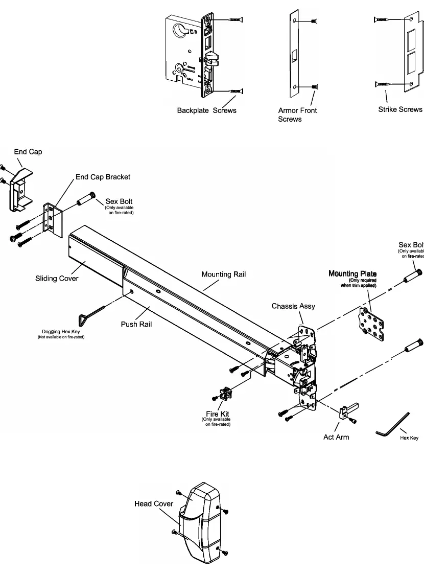
Parts Overview
The device consists of several key components, including the mortise lock, chassis assembly, push rail, end cap, and mounting brackets. Refer to the exploded view in the manual to identify all parts before starting assembly.
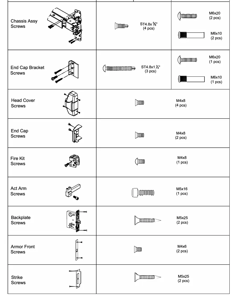
Screw Chart
The manual provides a detailed screw chart specifying the correct fasteners for metal and wood doors. Ensure you use the correct screw type (e.g., ST4.8x5/8" for metal, M6x20 for sex bolts) to ensure a secure installation.
Door Preparation
Before installing the device, you must prepare the door:
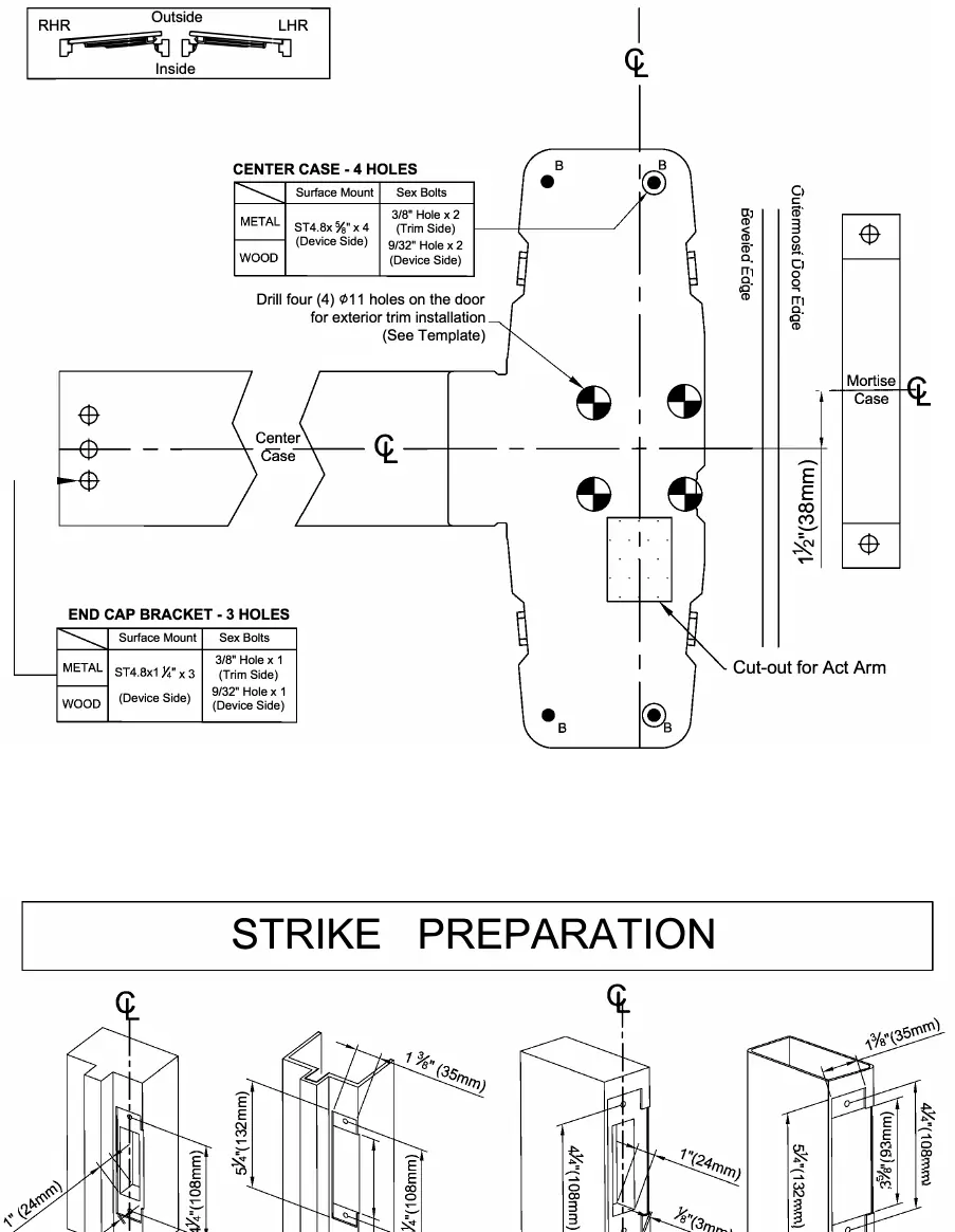
- Mark the horizontal centerline on the inside face of the door.
- Use the provided templates to mark the center case holes and end cap bracket holes.
- Drill the required holes for the center case and exterior trim.
- Ensure the backset dimension is 2 3/4" (70mm).
Installation Steps
- Prepare the door: Mark the horizontal centerline and drill holes according to the template.
- Install the mortise lock: Insert the lock into the door and fasten it with backplate screws.
- Install the mounting plate: Fix the mounting plate to the mortise lock.
- Install the trim: If using exterior trim, drill the necessary support holes and secure the trim.
- Install the act arm: Attach the act arm to the chassis assembly.
- Secure the chassis: Mount the device chassis assembly to the door.
- Install the strike: Mount the strike to the frame or the inactive door.
- Install the end cap: Attach the end cap bracket and end cap.
- Adjust the latch bolt: Ensure the proper gap between the act arm and the mortise case thumbpiece.
- Install the head cover: Attach the cover to the chassis assembly.
Handing Adjustment
The device handing can be changed for both ANSI and Fire-rated types. Follow the specific diagrams in the manual to rotate the handing components (180°) and reassemble the device for the desired handing (RHR or LHR).
Optional Features
- Dogging: Use the dogging hex key to turn the mechanism 90° clockwise while depressing the push rail to keep the latch retracted.
- Alarm Function: The device can be fitted with an optional alarm kit. Test the alarm by turning the key counterclockwise to activate and clockwise to deactivate.
Cutting the Device
If the device is too long for the door, it can be cut. Ensure a minimum clearance of 1 1/2" (38mm) between the frame and the device end (with the end cap removed). Cut the device square to ensure a proper end cap fit.
Practical help
Common problems
Device is too long for the door
Cut the device to the required length, ensuring the cut is square for proper end cap fit.
Latch bolt gap is incorrect
Adjust the gap between the act arm and the thumbpiece part of the mortise case.
Handing is incorrect
Follow the handing change procedure (14A or 14B) to rotate the internal components.
Before use
- Verify door handing (RHR or LHR).
- Confirm backset dimension is 2 3/4" (70mm).
- Check door material (metal or wood) to select correct screws.
- Ensure all templates are aligned correctly before drilling.
- Test the push rail and dogging function after installation.
Images and diagrams
- Screw Chart: Identifies the specific screw types and sizes required for metal versus wood door installations.
- Door Preparation Chart: Shows the exact drilling locations for the center case and end cap bracket.
- Handing Change Diagrams: Illustrates the disassembly and reassembly steps to switch between RHR and LHR.
Model compatibility
- Compatible with both metal and wood doors.
- Optional alarm kit and cylinder dogging kit available.
- Fire-rated and standard ANSI types have different handing change procedures.

Manual page author
David Miller
Documentation analyst
Organizes user manual content into clear summaries, with attention to model details, product context, and everyday usability.