Automotive / Garage Equipment
User Manual for TradeQuip 1891T Engine Stand
Comprehensive user manual for the TradeQuip 1891T Engine Stand. Includes assembly instructions, safety guidelines, maintenance procedures, parts diagram, and technical specifications.
Quick answers from the manual
Quick answer
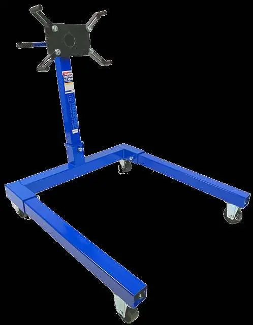
- The TradeQuip 1891T is an engine stand with a 680kg capacity, featuring a 360-degree swiveling head and adjustable mounting arms. p. 1
Key actions
- Assemble the stand by attaching legs, castors, and the main post as detailed in the assembly section. p. 5
First start
- Conduct a visual inspection for damaged parts, ensure the floor is level, and verify all bolts are tight before use. p. 4
Problems and fixes
Damaged or worn parts
Remove from service until repaired by an authorized service agent.
p. 5Maintenance and reset
- Keep the stand clean and perform annual inspections by an authorized repair facility. p. 5
Technical specifications
| Parameter | Value | Meaning | Pages |
|---|---|---|---|
| Safe Working Capacity | 680kg | Maximum load weight | p. 1 |
Where to find it in the PDF
- Specifications p. 1
- Assembly p. 5
- Parts Diagram p. 6
Table of contents
Manual images
Click an image to enlargeQuick Guide
The TradeQuip 1891T is a heavy-duty engine stand designed to support engines during repairs. Before use, ensure the stand is on a firm, level surface and that the engine dimensions fit within the stand's legs. Always wear safety glasses and protective clothing when operating the equipment.
Specifications
- Safe Working Capacity: 680kg
- Operating Height: 895mm
- Dimensions: 800mm (Width) x 870mm (Length)
- Nett Weight: 39kg
Assembly
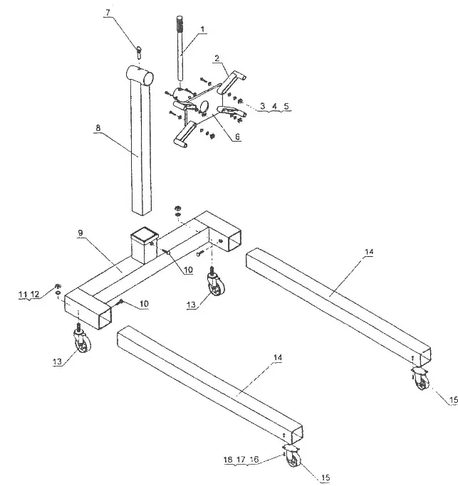
- Bolt the two 390mm castor wheels (17) to the front legs (14) using bolts (15) and nuts (18).
- Attach two 75mm castors (11) to the rear of legs (14) using nuts (13) and lock washers (20).
- Assemble the two legs (14) to the rear beam (10) using bolts (19), nuts (13), and flat washers (12).
- Attach the main post (03) to the rear beam (10) using bolts (09), bolt (19), nuts (13), and flat washers (12).
- Insert the engine mounting plate (06) through the tube at the top of the main post. Rotate until holes align and insert the ringed pin (01).
- Insert the handle (02) through the hole in the turning plate tube.
- Attach the shifting stands (07) to the rotating head (06) using bolts (08), flat washers (05), and nuts (04).
- Check all bolts for tightness before operating.
Safety and Operation
Pre-operational checks: Always conduct a visual inspection for cracked joints, damaged, loose, or missing parts before use. Do not operate if the unit is damaged.
Operating instructions:
- Ensure the engine is centered and securely mounted on the locking plate.
- Lock the mounting plate in position before fixing a load.
- To move a loaded stand, push from the load side (above the fixed wheels). Do not pull from the castor end.
- Never work under an engine mounted on the stand.
- Do not exceed the rated capacity of 680kg.
Maintenance
Keep the stand clean for optimal performance. Replace or repair damaged parts immediately using only recommended parts. Non-authorized parts may be dangerous and will invalidate the warranty. Annual inspection by an authorized repair facility is recommended.
Parts Diagram
Refer to the parts diagram in the manual for identification of components such as the main post, legs, castors, and mounting hardware. Ensure all parts are present and correctly installed according to the assembly instructions.
Manufacturer information
TradeQuip
Practical help
Common problems
Stand unstable or load not secure
Ensure the engine is centered, the mounting plate is locked, and the stand is on a firm, level surface.
Difficulty moving the stand
Push from the load side, above the fixed wheels. Do not pull from the castor end.
Damaged or worn parts
Remove from service immediately until repaired by an authorized service agent.
Before use
- Inspect for cracked joints or damaged parts.
- Ensure engine dimensions fit within the stand's legs.
- Verify all bolts are tight.
- Wear safety glasses and protective clothing.
- Ensure the floor is level and not slippery.
- Ensure non-essential persons are at a safe distance.
Specs in practice
- Safe Working Capacity
- The maximum weight the stand can safely support (680kg).
- Operating Height
- The height of the mounting head from the ground (895mm).
Images and diagrams
- The parts diagram illustrates the assembly of the main post, rear beam, legs, and castor wheels.
- It identifies the mounting head components, including the turning plate and shifting stands.
Model compatibility
- Engine dimensions must be within the legs of the engine stand.

Manual page author
Emily Carter
User documentation editor
Prepares concise manual descriptions and highlights the most useful setup, operation, and maintenance information for readers.