Tools / Lifting Tools
User Manual for TradeQuip 2058T Auxiliary Lifter
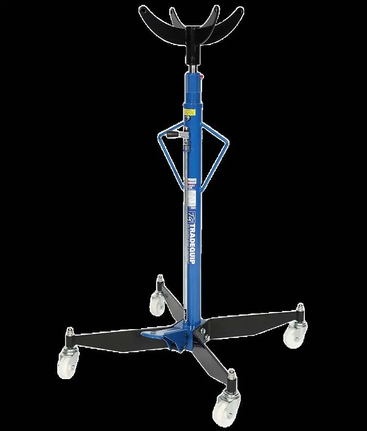
Comprehensive user guide for the TradeQuip 2058T Auxiliary Lifter. Includes assembly instructions, safe operating procedures, maintenance guidelines, and troubleshooting steps for this 500kg capacity under-hoist stand.
Quick answers from the manual
Quick answer
- The TradeQuip 2058T is a 500kg capacity auxiliary lifter designed for under-hoist support of vehicle components. It features a manual hydraulic system and requires air purging before first use. p. 1, 4
Key actions
- Purging air from the hydraulic system p. 4
- Lowering the load p. 5
First start
- Open breather valve, allow oil to settle for one hour, and purge air from the system. p. 4
Problems and fixes
Unit fails to extend
Check fluid level and fill if necessary.
p. 7Maintenance and reset
- Replace hydraulic oil annually. p. 6
Technical specifications
| Parameter | Value | Meaning | Pages |
|---|---|---|---|
| Safe Working Capacity | 500KG | Maximum load capacity | p. 1 |
| Working Height | 1175-1985 mm | Operating height range | p. 1 |
Where to find it in the PDF
- Specifications p. 1
- Assembly and Operation p. 4
- Parts List p. 8, 9
Table of contents
Manual images
Click an image to enlargeQuick guide from the manual
The TradeQuip 2058T is a 500kg capacity auxiliary lifter designed for under-hoist support of vehicle components. Before first use, you must open the breather valve and purge air from the hydraulic system. Always operate on a stable, level, and dry surface. Do not use this device as a stand-alone transmission lifter.
Safety Warnings
- Capacity: Do not exceed the maximum lifting load of 500kg.
- Surface: Use only on stable, level, smooth, and dry surfaces. Do not use on tarmac or soft surfaces.
- Usage: This is an auxiliary aid for component removal/installation. Do not use for other purposes.
- Personal Protection: Wear safety glasses, safety footwear, and protective clothing. Keep long hair contained.
- Dynamic Loading: Avoid sudden loading movements which can cause product failure.
Assembly
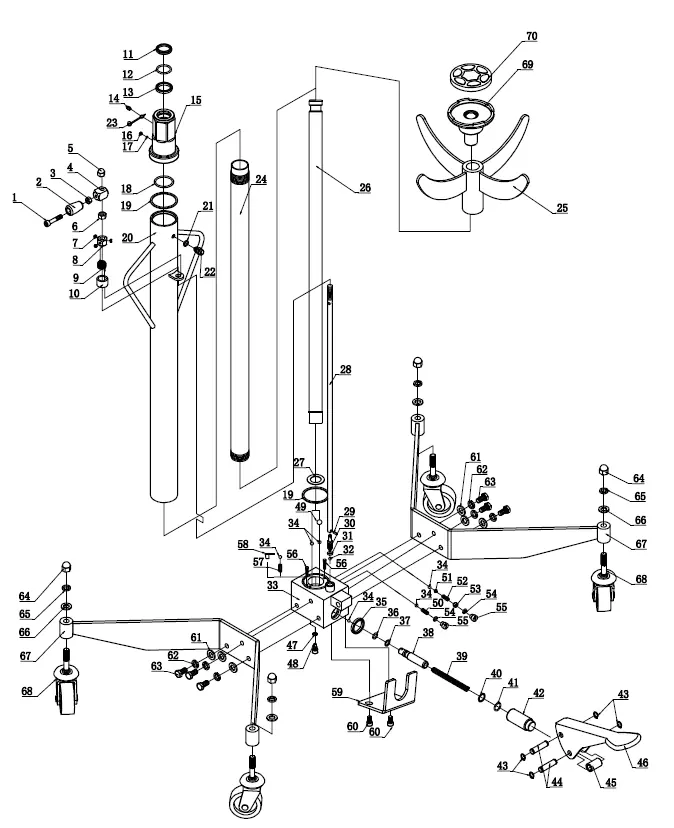
- Attach the two legs (67) to the base (33) using bolts (63), lock washers (62), and washers (61).
- Fit the four castors (68) to the legs (67) using nuts (64) and washers (65).
- Place the saddle (25) onto the top of the piston rod (26).
Before Use
Ensure the breather valve is open. Allow the lifter to sit for one hour to let oil settle. To purge air: open the air vent screw (22) at least one full turn, hold the release handle (02) to the right, and pump the foot pedal (46) 15 to 20 times.
Operation
- Roll the lifter into position and pump the foot pedal (46) until the saddle (25) reaches the desired height.
- Center the load on the saddle and ensure it is stable.
- To lower, slowly and carefully turn the release handle (02) to the right. The speed of descent is controlled by how far the valve is opened.
Maintenance
- Lubrication: Periodically lubricate pivot points, axles, and hinges with light lubricating oil or bearing grease.
- Cleaning: Keep the unit clean. Clean the piston rod with a clean oiled cloth; never use sandpaper or abrasive materials.
- Oil Level: Check hydraulic oil level annually. Drain and replace oil at least once a year. Use high-quality hydraulic jack oil only.
- Storage: Store in a dry location with the saddle fully lowered and the air vent valve closed.
Troubleshooting
If the unit fails to extend or has spongy response, check the fluid level and purge air from the system. If the unit fails to extend when pumped, check for release handle malfunction or contamination. If the cylinder does not retract, check for binding or contamination.
Parts List
The manual includes a detailed exploded diagram and a corresponding parts list table identifying components such as the pump base, piston, saddle, castors, and various seals and O-rings.
Manufacturer information
TradeQuip
Practical help
Common problems
Unit fails to extend or extends partially
Check for low fluid level and fill to the correct level.
Incomplete or spongy cylinder response
Fill to correct fluid level, purge air from the system, or check for low pressure.
Unit fails to extend when foot pedal is pumped
Check for release handle malfunction or internal contamination; disassemble and clean if necessary.
Cylinder does not retract or retracts slowly
Check for release handle malfunction, binding cylinder, or contamination.
Before use
- Ensure the breather valve is open.
- Allow the lifter to sit for one hour to let oil settle.
- Purge air from the hydraulic system.
- Inspect for cracked welds, leaks, or damaged/loose parts.
- Ensure the surface is stable, level, and dry.
Specs in practice
- Safe Working Capacity
- 500KG maximum load.
- Working Height
- 1175mm to 1985mm.
- Gross Weight
- 37KG.
Images and diagrams
- The parts diagram illustrates the assembly of the hydraulic pump base, piston rod, saddle, and leg/castor configuration.
Model compatibility
- Not intended for supporting loads as a stand-alone transmission lifter.
- Use only on stable, level, smooth, dry surfaces.

Manual page author
Emily Carter
User documentation editor
Prepares concise manual descriptions and highlights the most useful setup, operation, and maintenance information for readers.