Lighting / Controllers & Dimmers
Karlik 11MRO-2 Electronic Dimmer Switch
Quick guide for the Karlik 11MRO-2 electronic dimmer switch. Learn how to install, configure minimum light levels, and switch between operating modes for optimal LED performance.
Table of contents
Manual images
Click an image to enlargeQuick guide from the manual
The Karlik 11MRO-2 is an electronic dimmer switch designed for LED lamps, halogen lights (with electronic transformers), and incandescent bulbs. It features a push and rotary button for light intensity adjustment. Before first use, the device requires configuration to learn the connected lighting characteristics.
Technical Specifications
- Power supply: 230V~ 50Hz
- LED load capacity: 0-100W (max 10 dimmable LED bulbs)
- Halogen/Incandescent load: 10-250W
- Protection index: IP20
- Operating temperature: -20°C to +45°C
- Installation: Standard flush-mounted wall box (60mm)
- Connection: 3 clamps, max 1.5 mm² cable cross-section
Installation
- Deactivate the main fuses of the home installation.
- Verify the presence of a phase wire in the installation box.
- Remove the regulatory button using a screwdriver.
- Push the clips on the side walls of the external adapter to remove it.
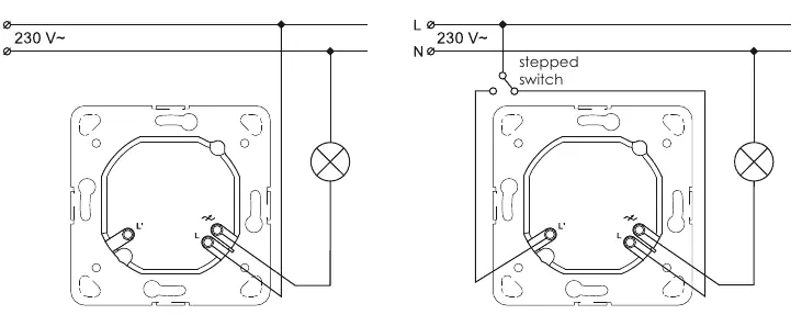
- Connect the phase wire to the clamp marked with 'L'.
- Connect the other wire to the clamp marked with an arrow. For dual-circuit systems, connect the third and fourth wires to the clamp with the arrow.
- Secure the dimmer module in the installation box using resilient clips or fastening screws.
- Assemble the external frame.
- Reattach the dimmer and control button.
- Activate the main fuses and perform functional tests.
Programming
Configuration of Minimum Light Level
If the light flashes during dimming, the minimum light level must be increased:
- Switch off the controller and turn the knob to the MINIMUM position (all the way left).
- Restart the regulator 3 times with a 1-second interval between switching on and off.
- The light will flash, indicating it is in CONFIGURATION mode.
- Within 3 seconds, turn the knob right until the light switches on and set the desired minimum level.
- Leave the controller for 3 seconds to save the setting.
Changing Operation Mode
If the regulator does not operate properly (e.g., flashing), change the mode:
- Switch off the controller and turn the knob to the MAXIMUM position (all the way right).
- Switch off and on 3 times with 1-second intervals.
- The light will flash, indicating CONFIGURATION mode.
- To select Mode 1: Turn the knob to MINIMUM, then back to MAXIMUM within 3 seconds.
- To select Mode 2: Turn the knob to MINIMUM within 3 seconds.
- The light will turn on once for Mode 1, or twice for Mode 2, confirming the setting.
Components
The device consists of the following parts:
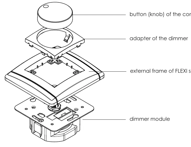
- Button (knob): Used for switching and dimming.
- Adapter: Secures the button to the module.
- External frame: FLEXI series frame.
- Dimmer module: The core electronic unit installed in the wall box.
Practical help
Common problems
Light flashing during dimming
Increase the minimum light level setting using the programming procedure.
Regulator not working properly
Change the operating mode from Mode 2 to Mode 1, or vice versa.
Device switches off automatically
This indicates an overload or short-circuit protection trigger; check the total load.
Before use
- Ensure the light source is dimmable (LED, halogen with electronic transformer, or incandescent).
- Verify the total load is within 0-100W for LEDs or 10-250W for other bulbs.
- Ensure the installation box is a standard flush-mounted box (60mm).
- Deactivate main fuses before starting installation.
- Ensure the installer is a suitably qualified person.
Specs in practice
- LED load capacity
- Supports 0-100W total, with a maximum of 10 dimmable LED bulbs.
- Protection index IP20
- Protected against solid objects over 12mm; not waterproof, for indoor use only.
- Voltage supply
- Standard 230V~ 50Hz mains power.
Images and diagrams
- Typical electricity connection: Standard wiring for a single dimmer control.
- Connection in a stepped system: Wiring diagram for two-way control using a stepped switch.
Model compatibility
- Does not work with halogen lights powered by magnetic or toroidal transformers.
- Do not connect two regulators in a two-way system as it may damage them.

Manual page author
Michael Turner
Technical manual editor
Reviews PDF manuals for structure, safety notes, and practical product details so readers can find the right information quickly.