Electronics / Networking
User Guide for Ubiquiti EdgeSwitch 16 XG
Quick start guide for the Ubiquiti EdgeSwitch 16 XG. Includes installation instructions, port configuration, LED status indicators, factory reset procedures, and technical specifications.
Table of contents
Manual images
Click an image to enlargeQuick Start Guide
This guide provides instructions for the installation and configuration of the Ubiquiti EdgeSwitch 16 XG. Ensure you have all required tools and cabling before beginning the installation.
Package Contents
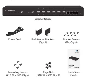
- EdgeSwitch XG
- Power Cord
- Rack-Mount Brackets (Qty. 2)
- Bracket Screws (M4, Qty. 8)
- Mounting Screws (#10-32 x 5/8", Qty. 4)
- Cage Nuts (#10-32 x 5/8", Qty. 4)
Installation Requirements
- Phillips screwdriver for rack or wall mounting.
- Standard 19-inch rack with at least 1U of height.
- Category 6A (or above) UTP cabling for indoor use.
- Shielded Category 6A (or above) cabling for outdoor applications, grounded through the AC ground of the power supply.
- Compatible fiber SFP+ modules for fiber optic connections.
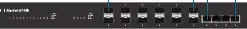
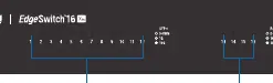
Hardware Overview
The front panel features 12 SFP+ ports (1/10 Gbps) and 4 RJ45 ports (1/10 Gbps). The back panel includes the AC power input, a DC power input for redundant power, and a console port for CLI management.
Hardware Installation
The switch can be placed on a horizontal surface, mounted on a wall, or installed in a rack.
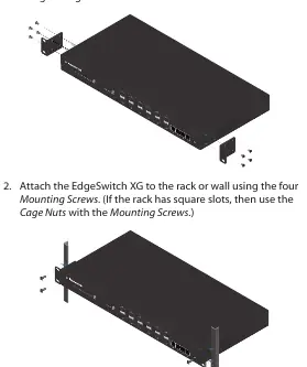
- Attach the Rack-Mount Brackets to the switch using the eight Bracket Screws.
- Secure the switch to the rack or wall using the four Mounting Screws. If the rack has square slots, use the provided Cage Nuts.
- Ensure at least 20 mm of clearance next to the ventilation holes to prevent fire hazards.
Connecting Power
Connect the included Power Cord to the AC power port. The switch also supports a redundant DC power source (25VDC, 56W minimum) via the DC Input port.
Connecting SFP+ and RJ45
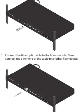
For SFP+ ports, remove the protective plug, insert a compatible fiber module, and connect the fiber optic cable. For RJ45 ports, connect standard Ethernet cables from your devices to the switch ports.
Accessing the Configuration Interface
The switch is set to DHCP by default. If it fails to obtain an IP address, it uses the fallback IP address 192.168.1.2.
- Connect your computer to the switch.
- If using the fallback IP, configure your computer's Ethernet adapter with a static IP on the 192.168.1.x subnet.
- Open a web browser and enter the IP address.
- Log in using the default credentials: Username ubnt, Password ubnt.
- Accept the license agreement to access the interface.
Resetting to Factory Defaults
There are two methods to reset the switch:
- Runtime Reset: While the switch is running, press and hold the Reset button. The System LED will turn blue after 3 seconds. Continue holding for about 15 seconds until the System LED flashes blue.
- Power-on Reset: Disconnect power. While holding the Reset button, connect power and continue holding for about 15 seconds until the System LED flashes blue.
Specifications
- Dimensions: 443 x 221 x 43 mm
- Weight: 2.62 kg (without brackets)
- Total Non-Blocking Line Rate: 160 Gbps
- Operating Temperature: -5 to 40° C
- Power Method: 100-240VAC or 25-16VDC
Safety Notices
Do not expose the switch to rain or moisture. Ensure proper ventilation. Do not use the device during an electrical storm. There are no operator-serviceable parts inside.
Practical help
Common problems
Cannot access the configuration interface
Ensure your computer is on the 192.168.1.x subnet if using the fallback IP 192.168.1.2. Check if your DHCP server assigned a different IP address to the switch.
Switch not booting or resetting
Ensure the power cable is securely connected. If performing a factory reset, ensure you hold the Reset button for the full 15 seconds until the LED flashes.
Before use
- Phillips screwdriver
- 19-inch rack (1U height)
- Category 6A or higher Ethernet cabling
- Compatible SFP+ fiber modules
- Grounded power outlet
Specs in practice
- Total Non-Blocking Line Rate
- 160 Gbps throughput capacity.
- Operating Temperature
- -5 to 40° C (23 to 104° F).
- Power Method
- Supports 100-240VAC or 25-16VDC redundant power.
Images and diagrams
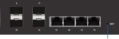
- Front Panel: Identifies SFP+ and RJ45 ports and status LEDs.
- Back Panel: Shows Console port, DC input, and AC power input.
- Rack Mounting: Illustrates bracket attachment and rack installation.
Model compatibility
- Requires CAT6A or above cabling for all Ethernet runs.
- SFP+ ports require compatible fiber modules.
- Outdoor installations require shielded cabling and proper grounding.

Manual page author
Emily Carter
User documentation editor
Prepares concise manual descriptions and highlights the most useful setup, operation, and maintenance information for readers.